
On my earlier posting “Power supply current
source-to-sink crossover characteristics” I showed what the effects on the
output voltage of a unipolar two-quadrant-power supply were, resulting from the
output current on the power supply transitioning between sourcing and sinking.
In that example scenario, the power supply was maintaining a constant output
voltage and the transitioning between sourcing and sinking current was dictated
by the external device connected to and being powered by the power supply. This
is perhaps the most common scenario one will encounter that will drive the
power supply between sourcing current and sinking current.
Other scenarios do exist that will drive a unipolar
two-quadrant power supply to transition between sourcing and sinking output
current. One scenario is nearly identical to the earlier posting. However, instead
of the device transitioning its voltage between being less and greater than the
power supply powering it, the power supply instead transitions its voltage between
being less and greater than the active device being normally powered. A set up for evaluating this scenario on an
Agilent N6781A two-quadrant DC source is depicted in Figure 1.
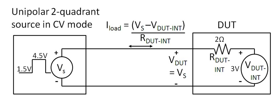
Figure 1: Evaluating current source-to-sink crossover on
an N6781A operating in constant voltage
In this scenario having the DC source operating as a
voltage source and transitioning between 1.5 and 4.5 volts causes the current to
transition between -0.75 and +0.75A. The
voltage and current waveforms captured on an oscilloscope are shown in Figure
2.

Figure 2: Voltage and current waveforms for the set up in
Figure 1
The waveforms in Figure 2 are as what should be expected.
The actual transition points are where the current waveform passes through zero
on the rising and falling edge. An expanded view to the current source-to-sink
transition is shown in Figure 3.

Figure 3: Expanded voltage and current waveforms for the
set up in Figure 1
As can be seen the voltage ramp transitions smoothly at
the threshold point, or zero crossing point, of the current waveform. The
reason being is that the DC is maintaining its operation as a voltage source.
Its voltage feedback loop is always in control.
Yet one more scenario that will drive a unipolar
two-quadrant source to transition between sourcing and sinking current is
operate it as a current source and program is current setting between positive
and negative values. In this case the device under test that was used is a
voltage source. One real-world example
is cycling a rechargeable battery by alternately applying charging and
discharging currents to it. The set up for evaluating this scenario, again
using an N6781A two-quadrant DC source is depicted in Figure 4.

Figure 4: Evaluating current source-to-sink crossover on
an N6781A operating in constant current
For Figure 4 the N6781A was set to operate in constant
current and programmed to alternately transition between -0.75A and +0.75A
current settings. The resulting voltage and current waveforms are shown in
Figure 5.

Figure 5: Voltage and current waveforms for the set up in
Figure 4
The waveforms in Figure 5 are as what should be expected.
The actual transition points are where the current waveform passes through zero
on the rising and falling edge. An expanded view to the current source-to-sink
transition is shown in Figure 6.

Figure 6: Expanded voltage and current waveforms for the
set up in Figure 4
As the N6781A is operating in current priority the
interest is in how well it controls its current while transitioning through the
zero-crossing point. As observed in Figure 6 it transitions smoothly through
the zero-crossing point. The voltage performance is determined by the DUT, not
the N6781A, as the N6781A is operating in constant current.
So what was found here is, for a unipolar two-quadrant DC
source, transitioning between sourcing and sinking current should generally be
virtually seamless as, under normal circumstances, should remain in either
constant voltage or constant current during the entire transition.
While testing this unit what is the length and gauge of the cable used between two units in the figure?
ReplyDeleteThe cable used was approximately 3 feet of 12 AWG.
ReplyDelete