
Hi everyone,
September has been a hectic month here at Keysight’s Power Supply Headquarters (to
give you an idea of the kind of month it has been, my dog literally ate my
passport a week before I left on an international trip) but I am back with another blog post for your reading pleasure. Today we are going to
talk about how to properly wire your power supply.
This is a common question. Wiring is
something that on the surface seems like it should be really easy but when you
dig a little deeper there are many layers to consider. The repercussions can be pretty severe as
well. With improper wiring, you can make
a high performance power supply seem like a low performance benchtop
supply.
First, let's talk about the things repercussions of improper wiring. The first and probably most undesired result is that your voltage will be unstable.
I have seen this in my own former career as a test engineer. The inductance from our wiring coupled with
some capacitance in our test equipment resulted in an oscillation that caused a
test to fail. We spent a Saturday
chasing this down and fixed it by properly wiring our system.
The second undesired result is that your voltage rise time and fall times could be much longer than specified. This will negatively affect your test throughput which in high volume manufacturing test could cost money due to increased test time. Properly wiring your power supply will enable you to get the maximum throughput from your power supply.
The last repercussion that I'll discuss is voltage
overshoots and undershoots. You want these to be as small as possible. A large
overshoot can possibly damage your DUT especially if you do not have your over voltage properly set. A voltage undershoot could cause
your DUT to shut down due to a low voltage condition.
All of these are real pains when you are trying to get your test set up and running. There are ways to properly wire your system so you can get the maximum specs out of your power supply.
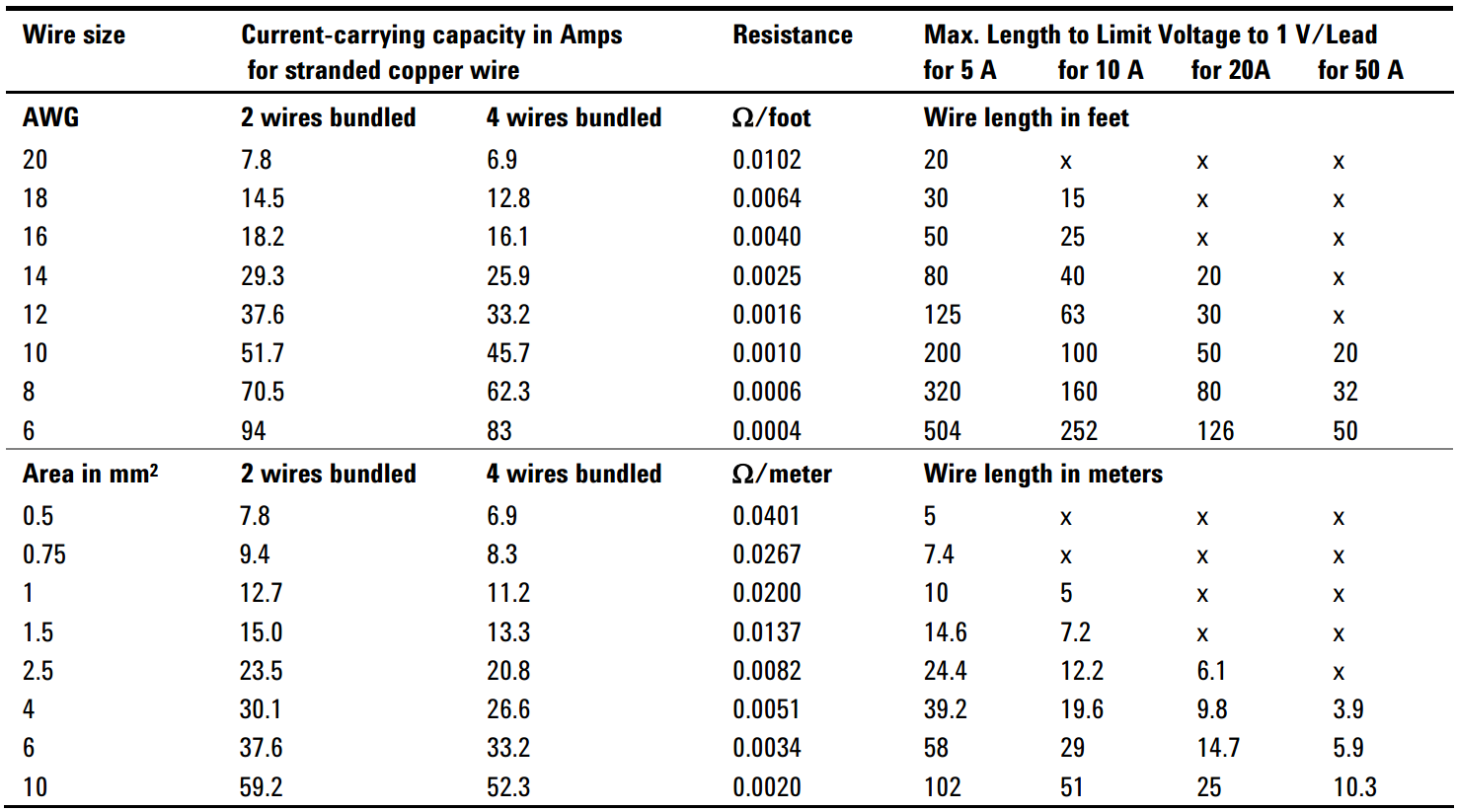
The first and most basic wiring tip is to keep the wiring as short as possible. The longer the wiring the higher the impedance from the wiring will be. The table below shows some specifications on some standard wire sizes:
The second tip is to use remote sensing. This will sense around all of the wiring drops from the wiring. This is good practice at all times. Remote sensing is cool.
The third tip is to twist your wires together. The key thing to remember her is that you twist the + and - output together and the + sense and - sense together. This will reduce the mutual inductance in the wires. Never, ever twist the sense and output leads together.
This is a picture of the spool of wire that we use for our sense wires here. You can see the the wires are very tightly twisted together here:

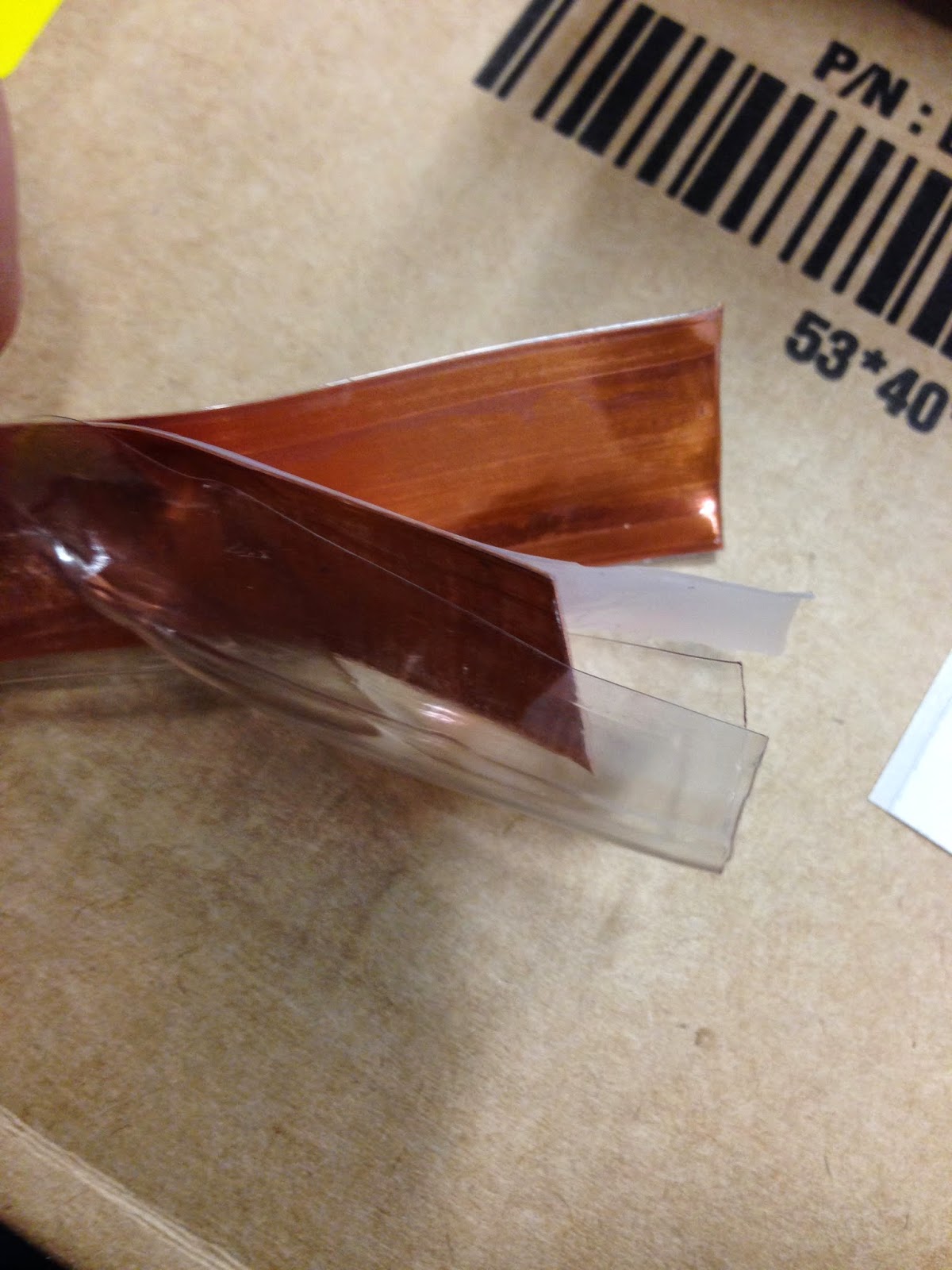
The other option is to use special low inductance wiring. If you look at the below picture, you can see that there are two flat conductors separated by an insulator. This reduces the mutual inductance even more than twisting the wires.:
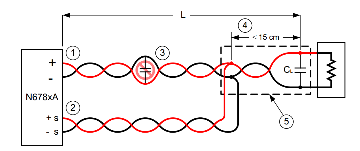
Our N678xA SMU DC Power Modules are very sensitive to how they are wired. Here is a diagram showing the proper wiring for the N678xA:

The top three items I mentioned should be standard practice when you set up your system. These are just great wiring practices. Sometimes you need to go the extra mile. Back when I was in the test group we followed all of these tips as best I could but due to the test system, we could not minimize the wire length enough. Our solution was to parallel more wires between the power supply and the load that we were using. Instead of one twisted pair, we used three twisted pairs in parallel. This also reduces the impedance of the wiring because you are paralleling the conductors (paralleled inductance and resistance reduces).
One of our design engineers wrote a very good article that touched on this subject a bit. You can check that out here: Article Link.
I hope that this is useful to everyone. Please let us know if you have any questions or comments.
No comments:
Post a Comment
Note: Only a member of this blog may post a comment.