
I was exploring some of the features on our new Keysight PA2201A IntegraVision power analyzer to better understand its operation and the applications for this new line of power measurement instrumentation. I had a simple desk lamp with a 100 W incandescent light bulb plugged into the wall outlet (120 Vac, 60 Hz here in the United States) and ran the voltage and current to the power analyzer. Given that the bulb presents a nearly pure resistive load to the sinusoidal voltage, as expected, the current was also a sine wave and in phase with the voltage. The power analyzer easily displays these measured waveforms.
What I never had an opportunity to see before was a visualization of the power waveform. For some reason, in all of my 35 years working in the power business, I never looked at a power waveform for a simple resistive load. Voltage? Sure! Current? Many times!! But power? Nope. The IntegraVision power analyzer shows voltage, current, and power waveforms as a typical display (this can be configured in quite a few other ways as well). So I was looking at the waveforms shown below.
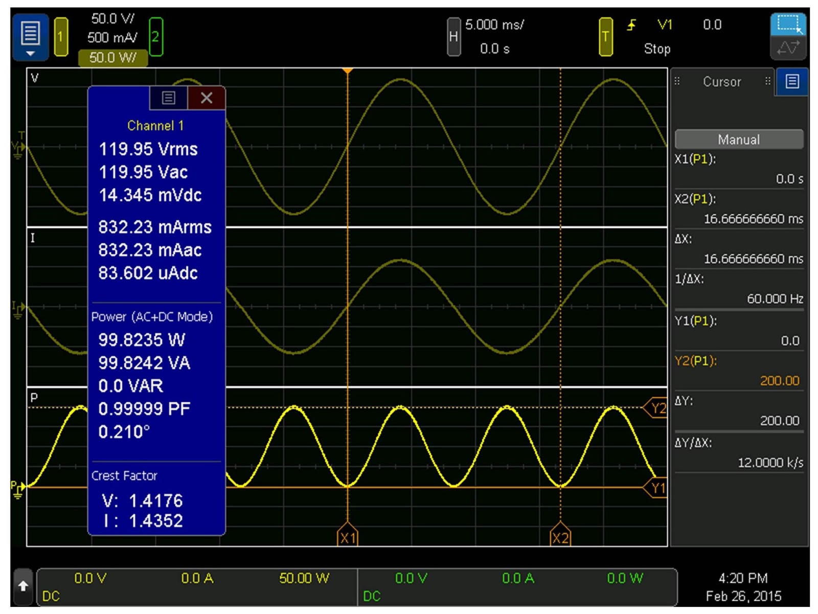
The first thing I noticed about the power waveform was that it was sinusoidal and it never went below zero. This quickly made sense to me since I did consider the bulb to be purely resistive meaning it is consuming power 100% of the time, so all of the power flowing to the bulb had to be positive. The bulb is never pushing power back to the AC line as would happen with a reactive load especially for a purely reactive load such as a pure capacitor or inductor. If the load (the bulb) was not purely resistive, some of the power waveform would have dipped below the zero power line indicating that sometimes the load was absorbing power and sometimes it was providing power back to the line.
The next thing I noticed about the power waveform was that its phase was synchronized with the voltage and current, and it showed twice the frequency. Again, this quickly made sense since the power is simply the product of the voltage and the current [P(t) = V(t) * I(t)]. So the positive peaks have to line up (they do), the zero crossings of the voltage and current have to align with zero watts on the power waveform (they do), and the negative peaks in the voltage and current have to line up with another positive peak in the power since a negative voltage times a negative current yields a positive power (they do). This, of course, was the reason for the power waveform being twice the frequency of the voltage and current waveforms.
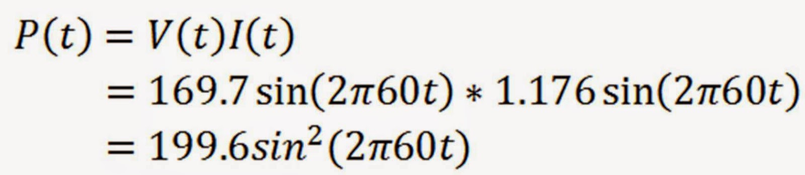
So I next decided to check the math behind the waveforms. I admit….I had to look up the trigonometric identity, but it was worth it! Since both the voltage and current waveforms are sine waves, and the power is the product of these, I looked up the identity for sine squared:
The voltage is a 120 Vrms, 60 Hz sine wave:

The current is 99.8 VA / Vrms = 0.832 Arms:
The power is V(t) * I(t):
Applying the above sine squared identity:
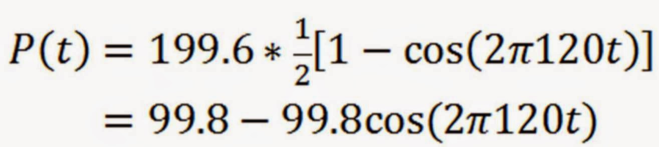
So you can see there is a 99.8 W fixed offset in the power waveform from which a cosine function is subtracted. The frequency of the cosine is 120 Hz (double the 60 Hz voltage and current waveforms). All of this completely agrees with the power waveform measured by the IntegraVision power analyzer. I am always thrilled when the math agrees with the measurements no matter how simple it is! How about you?
No comments:
Post a Comment
Note: Only a member of this blog may post a comment.