Showing posts with label Arbs. Show all posts

Friday, May 22, 2015

New performance options for the N6900A Advance Power System gives greater versatility for your test needs

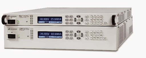
Our N6900 and N7900 series Advanced Power System (APS) DC power supplies are some of our most sophisticated products, setting new levels of performance and capabilities on many fronts. They come in 1kW and 2kW power levels as shown in Figure 1 and can be grouped together to provide much greater power levels as needed.


Figure 1: N6900 and N7900 Advanced Power System 1kW and 2kW models

Most noteworthy is that these can be turned into full two-quadrant DC sources by connecting up the optional 1kW N7909A Power Dissipator (2 needed for 2kW units) providing 100% power sinking capability. This makes APS an excellent solution for battery, battery management and many alternative energy applications, where both sourcing and sinking power are needed.
  • The N6900 series DC power supplies are designed for ATE applications where high test throughput and high performance is critical.
  • The N7900 series dynamic DC power supplies are designed for ATE applications where high speed dynamic sourcing and measurement is needed, in additions to high performance.

A lot more about these products is covered in another post on our General Purpose Electronic Test Equipment (GEPTE) blog when they were first announced. This is a great resource for learning more about APS and can be accessed from the following link: “New Advanced Power System: Designed to Overcome Your Toughest Test Challenges”

If you are a regular visitor to the “Watt’s Up?” blog no doubt you have seen we have shared a lot about how to do things with the N6900 series and N7900 series APS to address a number of difficult test challenges. A lot of times it would have otherwise required additional equipment or custom hardware to accomplish these tasks. While many of these examples are suitable for the N6900 and N7900, a good number of times examples make use of the additional capabilities only available in the N7900 series.

In certain test situations the N6900 series APS would be a great solution and lower cost than the N7900 series, if only it also had a certain additional capability. To this end Keysight has recently announced four new performance options for the N6900 series APS to address a specific test need you may have, as follows:
  1. Accuracy Package (option 301): Adds a second seamless measurement range for current
  2. Measurement Enhancements (Option 302): Adds external data logging and voltage and current digitizers with programmable sample rates
  3. Source and Speed Enhancements (Option 303): Adds constant dwell arbitrary waveforms and output list capability, and faster up and down programming speed
  4. Disconnect and Polarity-Reversal Relays (Option 760 and 761): Provides galvanic isolation and allows output voltage to be switched between positive and negative values
 Additional details about the N6900 series APS and the four new performance options are available from the recent press release, available at the following link: “Keysight Technologies adds Versatile Performance Options to Industry’s Fastest Power Supplies”

With these new options you now have a spectrum of choices in the Advanced Power System product family to better address any test challenges you may be faced with!

Tuesday, April 28, 2015

Optimizing a Power Supply’s Output Response Speed for Applications Demanding Higher Performance

Most basic performance power supplies are intended for just providing DC power and maintain a stable output for a wide range of load conditions. They often have lower output bandwidth to achieve this, with the following consequences:
  • Internally this means the feedback loop gain rolls off to zero at a lower frequency, providing relatively greater phase margin. Greater phase margin allows the power supply to remain stable for a wider range of loads, especially larger capacitive loads, when operating as a voltage source.
  • Externally this means the output moves slower; both when programming the output to a new voltage setting as well as when recovering from a step change in output load current.


While this is reasonably suited for fairly static DC powering requirements, greater dynamic output performance is often desirable for a number of more demanding applications, such as:
  • High throughput testing where the power supply’s output needs to change values quickly
  • Fast-slewing pulsed current loads where the transient voltage drop needs to be minimized
  • Applications where the power supply is used to generate power ARB waveforms


A number of things need to be done to a power supply so that it will have faster, higher performance output response speed. Primarily however, this is done by increasing its bandwidth, which means increasing its loop gain and pushing the loop gain crossover out to a higher frequency. The consequence of this the power supply’s stability can be more influenced by the load, especially larger capacitive loads.

To better accommodate a wide range of different loads many of our higher performance power supplies feature a programmable bandwidth or programmable output compensation controls. This allows the output to be set for higher output response speed for a given load, while maintaining stable operation at the same time. As one example our N7900A series Advanced Power System (APS) has a programmable output bandwidth control that can be set to Low, for maximum stability, or set to High1, for much greater output voltage response speed. This can be seen in the graph in Figure 1, taken from the APS user’s guide.


Figure 1: N7900A APS small signal resistive loading output voltage response

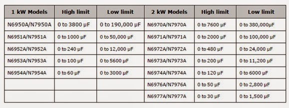
Low setting provides maximum stability and so it accommodates a wider range of capacitive loading. High 1 setting in comparison is stable for a smaller range of capacitive loading, but allowing greater response bandwidth. This can be seen in table 1 below, for the recommended capacitive loading for the N7900A APS, again taken from the APS user’s guide.


Table 1: N7900A APS recommended maximum capacitive loading

While a maximum capacitive value is shown for each of the different APS models for each of the two settings, this is not altogether as rigid and fixed as it may appear. What is not so obvious is this is based on the load remaining capacitive over a frequency range roughly comparable to the power supply’s response bandwidth or beyond. Because of this the capacitor’s ESR (equivalent series resistance) is an important factor. Beyond the corner frequency determined by the capacitor’s capacitance and ESR, the capacitor looks resistive. If this frequency is considerably lower than the power supply’s response bandwidth, then it has little to no effect on the power supply’s stability. This is the reason why the power supply is able to charge and discharge a super capacitor, even though its value is far greater than the capacitance limit given, and not run into stability problems, for example.

One last consideration for more demanding applications needing fast dynamic output changes, either when changing values or generating ARBs is the current needed for charging and discharging capacitive loads.  Capacitors increasingly become “short-circuits” to higher AC frequencies, requiring the power supply to be able to drive or sink very large currents in order to remain effective as a dynamic voltage source!

.

Tuesday, March 31, 2015

When is 64,000 points too many?

Hi everybody!

This month's blog post is based off a customer question that we received this month.  The question was around arbitrary waveforms (arbs), the number of points for the arb, and waveform fidelity.  I have spoken about arbs in the past: click me for Matt's old blog post.  Just to quickly reiterate, there are two options for arbs on the N6705 DC Power Analyzer and the N7900 Advanced power System. There is the Constant Dwell (CD) Arb that allows up to 64,000 point with a minimum Dwell time of 10 us per point and there is the standard List Arb that allows up to 512 points with a dwell as low as 1 us per point.

The question that we are trying to answer today is: When is 512 points more than 64,000 points?  It is an interesting question to think about.  It is definitely not true in cases where you have a non-repeating waveform.  The CD Arb will always be the preferred method there and will give you the best fidelity (smallest dwell times).

The answer is when you have long DC levels in your waveform.  Let's look at the proposed waveform below (please pardon the picture, I hand drew this on my tablet; also note that it is not to scale):


If you look at this waveform, the total time is 11.5 s.  It's a pretty simple waveform that goes from 4 V to 6 V with a 0.05 s ramp between the two values.  We need to pay attention to those times.

Lets with the math behind programming a CD Arb.  With a CD arb, there is a single dwell time so you basically sample the waveform 64000 times.  Lets use that to calculate a dwell time:

11.05 s/64000 = 172.66 us

This means that every point is going to last 172.66 us, no matter if it is in the constantly changing ramp or at a DC level.  This means that when the waveform is at 6 V for 10 s, you will use 57,918 points. That is 90% of your points just sitting at 6V!  For the 0.05 s ramp, you will only be using 290 points.  The ramp is where the waveform is actually changing but due to the nature of how the CD Arb works, you cannot increase the number of points allocated to the ramp.

Let's take a look at the 512 point list now.  We know that the first point of the list will be 4 V for 1 s and that the last point of the list will be 6 V for 10 s.  That leaves us with 510 points to do the 0.05 s ramp which results in s dwell time of 98 us.  This will give us more points in the ramp area and a better looking waveform overall.

That is all I have for this month.  Please feel free to use the comments if you'd like to get in touch with us.

Monday, July 14, 2014

Extending the usable bandwidth of the DC source when performing AC disturbance testing on your DUT

A lot of various products that run off of DC power, often destined to be used in automobiles and other types of vehicles, but even quite a number in stationary applications as well, require validation testing for impact of having AC disturbances riding on top the DC powering them.

 Conducting this type of testing is often a big challenge for the test engineer in finding a solution that adequately addresses the disturbance test requirements. It usually requires multiple pieces of hardware:
  • A DC power supply is used to provide the DC bias voltage and power.
  • A power amplifier is used to generate the AC disturbance.
  • A separate ARB /function generator is needed to produce the reference signal for the disturbance

Coupling the DC power supply and power amplifier together is extremely problematic. While it would be great to just directly connect the two in series, this rarely can be done in practice as the power amplifier usually cannot handle the DC current of the power supply. A variety of custom approaches are then typically taken, all with their associated drawbacks.

An article about this very topic was published last year, written by a colleague I work with, Paul Young in our R&D group. As he noted it’s great when the power source can provide both the DC power as well as the AC disturbance as this is a big savings over trying to incorporate multiple pieces of equipment. Paul’s article “Extending the Usable Bandwidth of a Programmable Power Supply for Generating Sinusoidal Waveforms” (click here to review) is an excellent reference on this and the inspiration for my blog posting this week.

Our N6705B DC Power Analyzer in Figure 1 and recently introduced N7900A series Advanced Power System (APS) 1KW and 2KW power supplies in Figure 2 have proven to be very useful for doing a variety of testing where transients and audio disturbances are needing to be introduced on top of the DC that is powering the DUT.


Figure 1: Agilent N6705B DC Power Analyzer and N6700 series DC power modules


Figure 2: Agilent N7900A series 1KW and 2KW Advanced Power System and N7909A Power Dissipator

The reasons for these products being useful for disturbance testing are due to their built in ARB generation capability in conjunction with having a respectable AC bandwidth, on top of being able to source the DC power. Everything can be done within one piece of equipment.

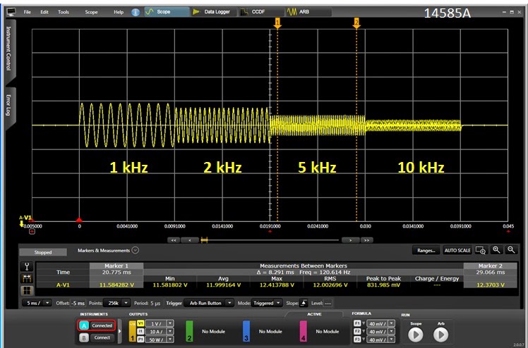
A very common test need is to superimpose a sinusoidal disturbance in the audio range. One example of this is in automobiles. The alternator “whine” AC ripple induced on top of the DC output falls within this category. Our 1KW and 2KW N7900A series APS are good for applications needing higher DC power. However, at first glance the specified AC bandwidth of 2 kHz on does not look like it would work well for higher audio frequencies. The AC response of an N7951A from 1 kHz to 10 kHz is shown in Figure 3. This was captured using the 14585A companion software to set up its ARB.  There is noticeable roll off for higher frequency, as expected.


Figure 3: N7951A APS AC response characteristics captured using companion 14585A software

However, it’s worth noting that the roll off is gradual and very predictable. In the case of superimposing a relatively small AC signal on top of the DC output it is easy to compensate by measuring the attenuation at the given frequency and applying a gain factor to correct for it, as I did as shown in Figure 4. As one example, for 5 kHz, I programmed 2.38 volts peak to get the desired 1 volt peak.


Figure 4: N7951A APS AC response characteristics after gain correction

As can be seen it was simple to now get a flat response over the entire range. A limiting factor here is sum of the programmed DC value plus programmed AC peak value needs to be within the voltage programming range of the power supply being used. In practice, when the AC disturbance is reasonably small it is easy to cover a wide range of frequency.

Another factor to consider is capacitive loading. Some DC powered products sometimes have a fairly substantial filter capacitor built in across the DC power input. This will increase the peak current drain from the power supply when AC is applied on top of the DC. As an example a 100 microfarad capacitor will draw a peak current of 6.28 amps when a 10 kHz, 1 volt peak AC signal is applied. There may also be series impedance limiting the peak current, but whatever this AC peak current is it needs to be included when determining the size of the power supply needed.

With these basic considerations you will be able to perform AC disturbance testing over a much greater bandwidth as well!

.

Friday, May 30, 2014

Arbs! Arbs! Arbs!

Hi everybody,

We have a new intern here and we have recently been talking about the arbitrary waveform capabilities (from now on I will refer to this as arbs)  of our power supplies and I thought that this would make an interesting blog post.  This is a really cool feature that we offer in our products as it give you the ability to create an alternating signal using our DC power supplies.  The two types of arbs are the LIST system and the constant dwell arb.

The LIST arb is a feature that we have in quite a few of our products.  The N6700 family, the N7900 family, and even some of our older power supplies have this feature.  The "Arb" system in the N6705 DC Power Analyzer is similar to the LIST.  These LISTs can contain as many as 512 different points with a timing resolution as low as 1 us.  Each point consists of a voltage or current setting and a time.  The times can be different for each point.  A short example of a programmed LIST is:

VOLT:MODE LIST
LIST:VOLT 10,25,5
LIST:DWEL 5,1,4

In the example above, the voltage will start out at 10 V and stay for 5 seconds, then transition to 25 V for 1 s and then go to 5 V for 4 s.  As you can see there are 3 voltage values with 3 corresponding dwell times.

The second mode for arbs that is only available on the N6705B DC Power Analyzer and the N7900 APS is call the Constant Dwell Arb (CD Arb).  In this mode, you can program as many as 64K points but all of the defined points have the same dwell time.  If we want to do the same waveform as above, we need to choose what will be our dwell time.  Since the smallest dwell I used in my example is 1 s, I will choose that.  Here is what a small part of the code would look like:

VOLT:MODE ARB
ARB:VOLT:CDW:DWEL 1
ARB:VOLT:CDW 10,10,10,10,10,25,5,5,5,5

The code above will produce the same waveform as the LIST example.  CD Arbs can get pretty unwieldy when you have a ton of points but we do offer some tools in our 14585A Control and Analysis software that allow you to import and export csv files to make life a bit easier.

There are advantages and disadvantages to both.  As you can see, in some cases it is easier to program a list since it requires less dwell points and gives you more flexibility with what your dwell can be.  If your waveform has a lot of DC levels in it, then the standard list might work for you.  If you have a long, complex waveform the 64 Kpoints offered in an arb will most likely offer you the best option to replicate your waveform.

Whichever arb you pick, this is a very powerful tool.  I am thinking that I will follow this up at a future date with more information about arbs.  If you have any questions, feel free to leave us some comments.