Showing posts with label fault indicator. Show all posts

Wednesday, March 20, 2013

Open sense lead detection, additional protection for remote voltage sensing


A higher level of voltage accuracy is usually always needed for powering electronic devices under test (DUTs). Many devices provide guaranteed specifications for operating at minimum, nominal, and maximum voltages, so the voltage needs to accurate as to not require unacceptable amounts of guard banding of the voltage settings.

One very significant factor that affects the accuracy of the voltage at the DUT is the voltage drop in the wiring between the output terminals of the power supply and the actual DUT fixture, due to wiring’s inherent resistance, as shown in Figure 1.


 A standard feature of most all system DC power supplies is remote voltage sensing. Instead of the voltage being regulated at the output terminals of the DC power supply’s output terminal, it is instead sensed and regulated at the DUT itself, compensating for the voltage drop in the wiring. Additional details of this are documented in an earlier posting: “Use remote sense to regulate voltage at your load”

While remote voltage sensing addresses the problem of voltage drop in wiring affecting the voltage accuracy at the DUT, it then raises the concern of what happens if one of the sense lines becomes disconnected. Will the DC power supply voltage climb up to it maximum potential causing my DUT to be damaged?  Although this is a very legitimate concern, often the voltage is usually kept within a reasonable range of the setting by a feature referred to as “open sense lead protection”. A deeper dive on the issue of open sense lines and open sense lead protection are discussed at our posting: “What happens if remote sense leads open?”

Even with open sense lead protection and the voltage being kept within a reasonable range of the setting, this can be a concern for some customers who are relying on a high level of DC voltage accuracy at the DUT for test and calibration purposes. One categorical example of this is battery powered devices, where ADC circuits that need to precisely monitor the battery input voltage have to be accurately calibrated. If the voltage from the DC power supply has significant error, the DUT will be miss-calibrated.

One issue with open sense lead protection is it is a passive protection mechanism. It is simply a back up that takes over when a sense line is open. There is no way of knowing the sense lead is open. No error flag is set or fault condition tripped. The voltage being read back is the same as that is being regulated by the voltage sensing error amplifier, which is the same as the set voltage, so all looks fine from a read-back perspective. This is where open sense lead detection takes over. Open sense lead detection is a system that actively checks to see if the sense lines are doing their job. If not it lets the test system know there is a fault.
Open sense detection is not a common feature for most system DC power supplies. As one example we do employ it in our 663xx series Mobile Communications DC Sources as these are used for powering, testing and calibrating battery powered wireless devices. In the case of an open sense line condition it generates a fault condition and it keeps the output of the DC source powered down. It also provides status information on which of the sense lines are open as well.

Friday, February 8, 2013

Protecting your DUT using a power supply’s remote inhibit and fault indicator features


Paramount in most any good electronic test system is the need to adequately protect the device under test (DUT), as well as the test equipment, from inadvertent damage due to possible faults with the yet-untested DUT, accidental misconnections, misapplication of power, and a large number of other unanticipated events that can occur. It is no surprise that a lot of these unanticipated events by nature are related to the powering of the DUT. For this reason good system DC power supplies incorporate a number of features designed to protect both the DUT, as well as the power supply, in the event of an unanticipated fault occurring.  Two related protection features incorporated into our DC system power supplies are the remote inhibit and the discrete fault indicator (RI/DFI). These features provide real-time protection enabling immediate shutting down the power supply, as well as enabling the power supply to take immediate action, on the event of detecting the occurrence of an unanticipated event or fault.

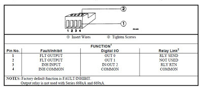
The remote inhibit is a digital input control while the discrete fault indicator is a digital output control signal, incorporated into the digital I/O port on our system DC power supplies. An example of a digital I/O port is illustrated in Figure 1. When the digital I/O port is configured for fault/inhibit (also called RI/DFI) pins 1 and 2 are the open collector and emitter of an isolated transistor, to serve as a digital output control, and pin3 and 4 are the digital input and common for the inhibit control input. The remote inhibit and the fault indicator can be used independently as well as in combination, for protecting the DUT.


Figure 1: Multi-function digital I/O port on Agilent 6600A series system DC power supplies

As the name implies, the remote inhibit is a digital control input, when activated, immediately disables the DC power supply’s output. One way this is commonly used is to connect an emergency shutdown switch that can be conveniently activated in the event of a problem. This may be a large pushbutton, or it may be a switch incorporated into a fixture safety cover. This arrangement is shown in Figure 2.


Figure 2: Remote inhibit using external switch

The fault indicator (i.e. FLT, FI, or DFI) digital output signal originates from the system DC power supply’s status system. The status system is a configurable logic system within the power supply having a number of registers that keep track of its status for operational, questionable, and standard events. Many of these events can be logically OR’ed together as needed to provide a fault output signal when particular, typically unanticipated, events occurs with the power supply. Items tracked by questionable status group register, like over voltage and over current, for example, are commonly selected and used for generating a fault output signal. An overview of the power supply status register system was discussed by a colleague in a previous posting. If you are interested in learning more; click here.
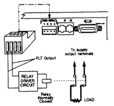
The fault indicator output can in turn be used to control an external activity for protecting the DUT, such as opening a disconnect relay to isolate the DUT, as one example, as depicted in Figure 3.


Figure 3: Fault output controlling an external disconnect relay

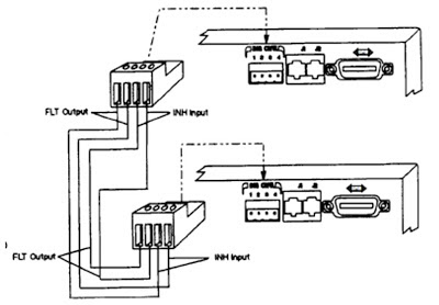
For DUTs that require multiple bias voltage inputs it is usually desirable that if a fault is detected on one bias input, that the other bias inputs are immediately shut down in conjunction with the one detecting a fault. The fault outputs and remote inhibit inputs on several DC power supplies can be used in combination by chaining them together, as depicted in Figure 4, to accomplish this task, to safeguard the DUT.


Figure 4: Chaining fault indicators and remote inhibits on multiple DC power supplies

The remote inhibit and fault indicator digital control signals on system DC power supplies provide a number of ways to disable power and take other actions for safeguarding the DUT. Their action is immediate, not requiring communication to, and intervention from, the test system controller. At the same time the system DC power supply generates status signals and can issue a service request (SRQ) to the test system controller so that it is notified of a problem condition and take appropriate correction action as well. The remote inhibit and fault indicator digital control signals are just two of many features found in many good system DC power supplies to assure the DUT is always adequately protected during test!