Showing posts with label inverter. Show all posts

Monday, October 15, 2012

Flyback Inverter for Fluorescent Lamp: Part 2, A Little Theory of Operation


In part 1 of this posting “Flyback Inverter for Fluorescent Lamp: Part 1, Making Repairs” a little careful and straightforward troubleshooting and repair brought my friend’s fluorescent lamp assembly back to life again. But a fluorescent lamp has quite a few unique requirements to get it to start up and stay illuminated. How does this flyback converter manage to do these things?

I had first looked around to see if I could find a schematic for this fluorescent lamp assembly, but nothing turned up for me. However, the parts count was low enough, and circuit board large enough, that it was a fairly simple matter to trace out and sketch the inverter’s schematic in fairly short order, as shown in Figure 1.


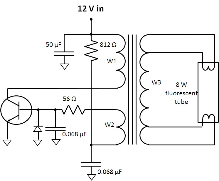
Figure 1: Fluorescent lamp single-ended flyback inverter circuit


When first powered up the switching transistor is biased on by the 812 ohm resistor, energizing transformer winding W1. This in turn applies positive feedback to the transistor through winding W2, driving it into saturation. There are two mechanisms in the flyback transformer that are critical for making this inverter work:
  • First it has a gapped core. This allows it to store a substantial amount of energy in its magnetic field which in turn gets dumped over to the fluorescent tube through the secondary winding W3 when the transistor turns off and the transformer’s magnetic field collapses.  During this period the winding voltage continues to climb as the magnetic field collapses until the energy can find a place to discharge to, in this case into the fluorescent tube. The voltage is also further increased by the turns ratio of the transformer. This is the “flyback” effect that creates sufficiently high enough voltage to get the fluorescent tube to “strike” or ionize its gas to get it to start conducting and give off illumination, typically many hundreds of volts.
  • As can be seen this inverter is a very simple circuit with a minimum of parts. A second mechanism in the transformer is it is designed to saturate in order to make the inverter oscillate. At the end of the transistor’s “on” period the transformer reaches its maximum magnetic flux at which point the transformer saturates. Winding voltage W2 drops to zero and then reverses driving the switching transistor into cutoff.  After the magnetic field has collapsed and energy discharged to the fluorescent tube the process repeats itself.


The switching transistor’s collector and base voltages during turn on are captured in the oscilloscope diagram shown in Figure 2.


Figure 2: Inverter switching transistor collector and base voltage waveforms

A number of interesting things can be observed in Figure 2.  The oscillation period is roughly 50 microseconds, or oscillation frequency of 20 kHz. It takes about 10 cycles, 500 microseconds, for the fluorescent tube to strike. During this initial phase the peak collector voltage is flying up to nearly 100 volts or about 8 times the DC input voltage being applied. Again, this voltage is being multiplied up by the turns ratio of windings W1 and W2 to bring this up in the vicinity of 600 volts or so needed to make the fluorescent tube to strike. Once the tube does strike and starts conducting its impedance drops. This causes the collector voltage to drop down to about 35 volts which is consistent with the proportion of drop in voltage needed for the fluorescent tube once it’s gas is ionized and is conducting. Note also the collector voltage pulse also widens as it takes a longer time for the energy in the transformer to be dumped when it’s at a lower voltage.

Although this inverter at first glance is a rather simple and minimum viable, minimum parts count circuit, with careful design it can be made to be very efficient. This is where the design of the transformer becomes as much art as science, knowing how the subtle characteristics of the magnetic material and inductive and capacitive parasitics can be used to advantage in contributing to and improving the overall performance of the design.

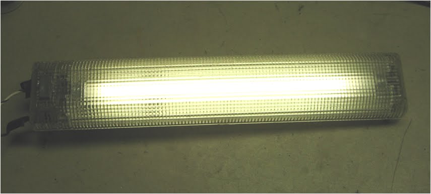
Anyway, what my friend really cared about is the lamp now works and he is able to put it to good use in his camper!

Thursday, October 4, 2012

Flyback Inverter for Fluorescent Lamp: Part 1, Making Repairs


A friend of mine approached me a while ago asking for some help. The fluorescent lamp assembly for his VW Westfalia camper was dead and, knowing I knew more about electronic devices than he did, figured it was worth challenging me with it.  I was actually happy to do so. Being involved with DC power conversion of a variety of forms I was always a bit curious to learn about how fluorescent lamp assemblies that were powered from low voltage DC worked anyway.

“My lamp does not work; can you look at it for me?”
“I suppose. Did it just stop working? Did you try anything to get it working again?”
“Well, it really never worked for me. I messed around with it a little but it did not help. I may have hooked it up backwards.”
“Why do you think you hooked it up backwards?”
“Well, it did not work so I tried reversing the power connections. That didn’t make it work however.”
“You really should not do that with electronic things!”

I took the lamp home and later when I had chance to look at it carefully I visually identified several problems. Like many other things I have repaired, a lot of the times it is not the device itself but rather a previous owner unintentionally inflicts unnecessary damage on it when attempting to make repairs.  In my friend’s partial defense, someone previously had already made unsuccessful attempts at trying to make it work again, unwittingly making things worse.

Referring to Figure 1 I unanchored the inverter circuit board from the back of the lamp assembly for closer inspection. It was immediately obvious there were problems that would keep it from working:
  • The connectors for the wiring to the fluorescent tube were not making contact.
  • A portion of a circuit board trace where the power feeds in was blown away.


Figure 1: Fluorescent lamp inverter board had obvious problems

Clearly someone had let the smoke out of it that made it work!  After making repairs to these problems I then tried powering it up using a power supply with a current limit to keep things safe. As I expected I was not going to get off that easy. The power supply went right up to its current limit setting. The lamp still did not work. 

The next step was to probe around the circuit board with a DMM.  With the abuse this lamp assembly has been subjected to I suspected the switching transistor would be damaged and sure enough it was measuring shorted. However, after removing it, it seemed to check out good. Probing around on the board again, a diode adjacent to the transistor measured shorted as well. Upon its removal it fell in half as a result of being overheated. I found where the rest of the smoke that makes it work had come out!  I replaced the diode, reinstalled the transistor and remounted the circuit board. Upon applying power again the result was a bit different as shown in Figure 2. I managed to reinstall all the smoke back into it again!


Figure 2: Fluorescent lamp assembly back in working order

While I had a general idea of how it works, now that I had the fluorescent lamp assembly working again I had take the opportunity to make some measurements and study the finer aspects of how it works, which I will cover, coming up in part 2. Stay tuned!

Wednesday, May 16, 2012

What Is Old is New Again: Soft-Switching and Synchronous Rectification in Vintage Automobile Radios


I have to admit I am a bit of a vintage electronics technologist.  One of many pass times includes bringing vintage vacuum tube automobile radios back to life. In working with modern DC sources I’ve seen innovations come about in the past decade for efficient power conversion, including soft switching and synchronous rectification. A funny thing however, for those who have been around long enough, or into vintage technologies like me, is that these issues and somewhat comparable solutions existed up to 70 years ago for automobile radios and other related electronic equipment. What is old is new again!

As we know, vacuum tubes (or valves to many) were to electronics back then as what semiconductors are to electronics today. The problem for portable and mobile equipment was that the vacuum tubes needed typically 100 or more volts DC to operate. They did have high voltage batteries for portable equipment but for automobiles the radio really needed to run off the 6 or 12 volts DC available from the electrical system. The solution: A DC/DC boost converter!

Up until the mid 1950’s most all automobile radios used vacuum tubes biased with high voltage generated from a rather primitive but clever DC/DC boost converter design. The inherent technological challenge was semiconductors did not yet exist to chop up the low-voltage, high-current DC to convert it to high-voltage, low-current DC. Of course if the semiconductors did exist this would all be a moot point! Making use of what was available the DC/DC boost converters employed what were called vibrators, which are a form of a continuously buzzing relay, to chop up the low-voltage DC for conversion. Maybe some of you are familiar with the soft humming sound heard when an original vintage automobile radio is turned on, prior to the vacuum tubes finally warming up and the audio taking over? That humming is the vibrator, the “heart” of the DC/DC boost converter in the radio.

Figure 1 below is an example circuit of vibrator-based DC/DC boost converter in a vintage automobile radio. This is just one of quite variety of different implementations created back then. Two pairs of contacts in the vibrator act in a push-pull fashion to convert the low-voltage DC into a low-voltage AC square wave. This in turn is converted to a high-voltage square wave by the transformer. Because the vibrator is an electro-mechanical device, it is limited in how fast it can switch. Switching frequencies are typically about 100 to 120 Hz. The transformers used are naturally the steel-laminated affairs similar in nature to the transformers used to convert household line voltage in home appliances. Very possibly some radio manufacturers used off- the-shelf appliance transformers in reverse to step up the voltage!  Often a small rectifier vacuum tube, such as a 6X4 (relatively modern, by vacuum tube standards) would be used to convert the high voltage AC to high voltage DC, but in this particular example I am showing here another two pairs of contacts on the secondary side switch simultaneously with the first pairs of contacts to rectify the high voltage AC. Highly efficient synchronous rectification, up to 70 years ago!

Figure 1: Representative DC/DC boost converter for a vintage automobile radio

The clever part of these DC/DC boost converters is making the vibrators last. Let’s see; 100 cycles/second, times 60 seconds/minute, times 60 minutes/hour, times ~2 hours/day, times 365 days/year; that’s 263 million cycles in one year! And while the vibrator was replaceable, it would often last for many years or more, which is quite remarkable. The trick was paying close attention to the switching as to not stress the vibrator‘s contacts. Referring to the waveforms in Figure 2, there is quite a bit of dead time between the non-overlapping switching of the contacts. This was by design. The capacitor across the secondary of the transformer in Figure 1 is carefully matched to ring with the transformer’s inductance such that the voltage is near zero across the alternate set of contacts is just as they’re closing, minimizing arcing and wear. Low-stress soft switching, again, up to 70 years ago! Ironically the cause for the vibrator failing was often due the capacitor degrading with stress and time. The capacitor was actually slightly larger than ideal value at the start to prevent overshoot and allow for aging. When resurrecting a vintage automobile radio frequently the vibrator will still work. Make certain to replace the capacitor first however or the vibrator is bound to have a very short second life.

Figure 2: Switching waveforms in a vibrator-based DC/DC boost converter

These vacuum tube automobile radios with vibrator-based DC/DC boost converters had quite a long run before being displaced, first for a very short period in the later 1950’s by hybrid radios using low voltage vacuum tubes and early germanium power transistors, and then finally overtaken by fully transistorized automobile radios in the early 1960’s.

So my hat’s off to the many design engineers of yesteryear who encountered such challenges, fully understood the principles, and just as creatively came up with solutions for them so long ago, based on what they had available. And again for those seasoned engineers who see such things come around yet once more as a new innovation, who humbly smile to themselves knowing that “what is old is new again”.

By chance are you a vintage electronics technologist?

Monday, January 30, 2012

Watts and volt-amperes ratings – what’s the difference and how do I choose an inverter based on them?

At the end of September, I posted about hurricane Irene and inverters. In that post (click here to read), I talked about the power ratings for inverters and just skimmed the surface about the differences between ratings in watts (W) and volt-amperes (VA). In this post, I want to go further into detail about these differences. Both watts and VA are units of measure for power (in this case, electrical). Watts refer to “real power” while VA refer to “apparent power”.

Inverters take DC power in (like from a car battery) and convert it to AC power out (like from your wall sockets) so you can power your electrical devices that run off of AC (like refrigerators, TVs, hair dryers, light bulbs, etc.) from a DC source during a blackout or when away from home (like when you are camping). Note that this power discussion is centered on AC electrical power and is a relatively short discussion about W, VA, and inverters. Look for a future post with more details about the differences between W and VA.

Watts: real power (W)
Watts do work (like run a motor) or generate heat or light. The watt ratings of inverters and of the electronic devices you want to power from your inverter will help you choose a properly sized inverter. Watt ratings are also useful for you to know if you have to get rid of the heat that is generated by your device that is consuming the watts or if you want to know how much you will pay your utility company to use your device when it is plugged in a wall socket since you pay for kilowatt-hours (power used for a period of time).

The circuitry inside all electronic devices (TVs, laptops, cell phones, light bulbs, etc.) consumes real power in watts and typically dissipates it as heat. To properly power these devices from an inverter, you must know the amount of power (number of watts, abbreviated W) each device will consume. Each device should show a power rating in W on it somewhere (390 W in the picture below) and you can just add the W ratings of each device together to get the total expected power that will be consumed. Most inverters are rated to provide a maximum amount of power also shown in watts (W) – they can provide any number of watts less than or equal to the rating. So, choose an inverter that has a W rating that is larger than the total number of watts expected to be consumed by all of your devices that will be powered by the inverter.


Volt-Amperes: apparent power (VA)
VA ratings are useful to get the amount of current that your device will draw. Knowing the current helps you properly size wires and circuit breakers or fuses that supply electricity to your device. A VA rating can also be used to infer information about a W rating if the W rating is not shown on a device, which can help size an inverter. Volt-amperes (abbreviated VA) are calculated simply by multiplying the AC voltage by the AC current (technically, the rms voltage and rms current). Since VA = Vac x Aac, you can divide the VA rating by your AC voltage (usually a known, fixed number, like 120 Vac in the United States, or 230 Vac in Europe) to get the AC current the device will draw. To combine the apparent power (or current) of multiple devices, there is no straightforward way to get an exact total because the currents for each device are not necessarily in phase with each other, so they don’t add linearly. But if you do simply add the individual VA ratings (or currents) together, the total will be a conservative estimate to use since this VA (or current) total will be greater than or equal to the actual total.


What if your device does not show a W rating?
Some electrical devices will show a VA rating and not a W rating. The number of watts (W) that a device will consume is always less than or equal to the number of volt-amperes (VA) it will consume. So if you need to size an inverter based on a VA rating when no W rating is shown, you will always be safe if you assume the W rating is equal to the VA rating. For example, assume 300 W for the 300 VA device shown in the picture above. This assumption may cause you to choose an oversized inverter, but it is better to have an inverter will too much capacity than one with too little capacity. An inverter with too little capacity will make it necessary for you to unplug some of your devices; otherwise, the inverter will simply turn itself off to protect its own circuitry each time you try to start it up, so it won’t work at all if you try to pull too many watts from it.

Some electrical devices will show a current rating (shown in amps, or A) and not a VA rating or W rating. Usually, this current rating is a maximum expected current. Maximum current usually occurs at the lowest input voltage, so calculate the VA by multiplying the current rating (A) times the lowest voltage shown on the device. Then, assume the device consumes an equal number of W as mentioned in the previous paragraph. For example, the picture below shows an input voltage range of 100 to 240 V and 2 A (all are AC). The VA would be the current, 2 A, times the lowest voltage, 100, which yields 200 VA. You could then assume this device consumes 200 W.

Friday, September 30, 2011

Hurricane Irene and inverters

During the weekend of August 27-28, 2011, hurricane Irene wreaked havoc along the east coast of the United States. I live in northern New Jersey where we got more than 10 inches of rain in a short time! Flooding, downed trees, and power outages were rampant! My mother called me during the storm to tell me her basement was flooded. She still lives in the house where I grew up, and I know that basement had not flooded in decades. But she lost power disabling her sump pump, so the heavy rain resulted in several inches of water in the basement saturating the carpet and ruining furniture and other personal items. What a mess! And my brother, who lives in another NJ town, has a restaurant that ended up with 4 feet of water in it!! Fresh fish, anyone?

So when my mother called me for help, I gathered up various tools, buckets, hoses, extension cords, flashlights, my wet/dry vac, and stopped at a friend’s house to borrow an inverter he used when camping (thanks, Andy!). An inverter takes DC in and puts out AC. My hope was to power the inverter from my car battery and plug in my mom’s sump pump to empty out the water in her basement. Luckily, as I was driving to her house with my friend who was coming to help (thanks, Nyla!), my mom called my cell phone to let me know the power was back on, so the sump pump kicked in and pumped out the bulk of the water. Of course, a soggy mess was left behind (7 hours of wet vacuuming made only a small dent in the cleanup, but it was a start). So, it turns out I did not use the inverter at her house (it would not have provided enough power anyway), but when I went to work the next week, I figured I’d play around with it in our lab area. Here are some of the things I found…

This inverter is a Coleman Powermate (model PMP400) 400 W inverter. It takes 12 V DC in and has a 40 A fuse on the input side, and two outlets with an on/off switch on the output side.


The output is a modified sine wave (looks more like a modified square wave to me, but OK, I’ll call it by its rightful name), at nominally 120 Vrms and 60 Hz, which are the standard AC mains voltage and frequency in the US. The waveform below was captured with a scope (an Agilent MSO7054A) and shows the actual output of the inverter with 12V DC in (from an Agilent N6754A installed in an N6705A) and a light load (~32 W) on the output.


Below is what the standard AC line looks like in the US, so you can see that the inverter's output (shown above) is only an approximation of the waveshape, although the inverter does maintain the correct rms voltage and frequency:


As a load on the inverter, I powered up another one of our DC power supplies (an Agilent 66332A) by plugging it into the inverter output. I could then program the output of the 66332A power supply to a voltage (20 V), connect it to one of our DC electronic loads (an Agilent 6063B) and vary the load current (up to nearly 5 A), thereby changing the loading on the 66332A, which in turn, changed the load on the inverter.


The inverter output frequency remained very close to 60 Hz for all loading conditions, and the output voltage dropped slightly (just a few volts) as I increased the loading on the inverter. The maximum power I drew from the inverter was limited by my input power source, the N6754A, which is a 300 W, 60 V, 20 A power supply. Since I was using it at 12 V, I set the current limit on it to the maximum of 20 A providing a maximum of about 240 W to the inverter input. So I was able to exercise the inverter up to only a little over one half of its 400 W capability.

The 66332A power supply I used as my load for the inverter has a standard AC input and seemed to operate just fine when powered by the modified sine wave coming from the inverter output. Regarding other loads you might plug into the output of an inverter, I think most AC motors would operate when supplied by a modified sine wave, however other devices such as audio equipment, fluorescent lighting, and some laser printers might not work properly or at all. Inverters are available with pure sine wave outputs to more closely mimic the power supplied by your utility company, however, these tend to be much more costly – sometimes several times the cost of an equally powered modified sine wave inverter.

I looked up a few numbers about waveforms and found that a pure square wave has a THD of about 45% while a modified sine wave has a THD of about 24%. Here is an interesting article on this topic:
http://powerelectronics.com/mag/608PET21.pdf

So if you ever lose AC mains power and need to run one or more AC powered devices, you could temporarily use an inverter powered from your car battery. Just be sure to get an inverter with enough power to handle the load you will put on it, and make sure the type of inverter you choose (modified or pure sine wave output) is appropriate for the load you want to power. Although it turned out I did not need it for my mom’s sump pump, the 400 W inverter I borrowed would not have been powerful enough for the pump. The current rating on the pump was about 6 A, so at 120 V, that is 720 VA (120 V x 6 A) which is more than the 400 W inverter could provide. But how do you compare VA (volt-amperes) to W (watts), you ask? The power that a device consumes expressed in W will always be less than or equal to the power in VA, but I’ll leave that discussion for another post! For now, if you think you’ll need an inverter, get one with a W rating higher than the total VA you require. This approach may be a bit overkill, but you will definitely have enough power.