Showing posts with label load regulation degradation. Show all posts

Wednesday, November 6, 2013

Paralleling power supplies for more power without compromising performance!

A year ago my colleague here, Gary, provided a posting “How can I get more power from my power supplies?” (Click here to review). He describes connecting power supplies in series for higher voltage or in parallel for higher current. Along with suggested set ups a list of requirements and precautions are also provided.

Connecting multiple power supplies in parallel operating as voltage sources is always problematic as there will be some imbalance of voltage between them. That’s why, in this previous posting, one unit operates as a voltage source and the remaining paralleled units operate in constant current. The compliance voltage limit of all the units operating in constant current need to be set higher than the master in operating in constant voltage in order to maintain this operation. This is illustrated in Figure 1.


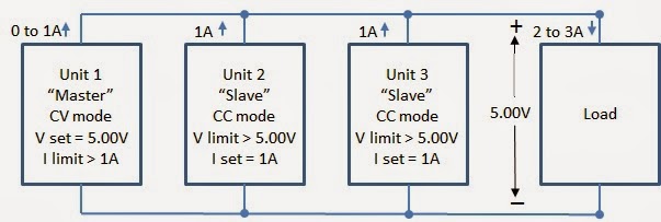
Figure 1: Operating power supplies in parallel for higher power


As long as a high level of loading is maintained the paralleled units remain in their respective operating modes (in this case at least 2/3 loading). However, what happens if you cannot maintain that high level of loading? It is possible in practice to operate at lighter loads with this approach. In this case it is important to set the voltage levels of all the units the same. Now what happens is when the units are fully loaded they operate as already described, with the lowest voltage unit remaining in constant voltage. But when they are unloaded the lower voltage units transition to unregulated operation and the highest voltage unit then maintains the overall output in constant voltage. This is shown in Figure 2, for 0 to 1/3 loading.


Figure 2: Conditions of power supplies connected in parallel at light loading

There is a bit of performance compromises as a result. The transition between the lowest and highest voltage limits adds to the voltage regulation. Also, due to different units experiencing mode crossover transitions between constant voltage, constant current and unregulated operating modes transient voltage performance suffers considerably.

An improvement on this direct paralleling approach is having a master-slave arrangement with control signals to maintain current sharing across units. Our N5700A and N8700A series power supplies use such a control arrangement as depicted in Figure 3, taken from the N5700A user’s guide.


Figure 3: N5700A Connection for parallel operation (local sensing used)

With this arrangement the master unit, operating in constant voltage, provides an analog current programming output signal to the slave unit, operating in constant current. In this way the two units equally share the load current across a wide range of load current.

Still, having multiple units with only one in constant voltage does not provide as good of dynamic performance as a single voltage source of higher power.  A unique and innovative approach was taken with our N6900A / N7900A series Advance Power System (APS) to support seamless parallel operation without compromising performance. The paralleling arrangement for our N6900A / N7900A series APS is depicted in Figure 4.


Figure 4: N6900A / N7900A series APS Connection for parallel operation

The N6900A / N7900A series APS paralleling arrangement also uses an analog control signal for driving current sharing. However with this arrangement there is no master or slaves. All units remain in constant voltage while equally sharing current. This provides the user with an easy way to scale a power system as required without having to worry about compromising performance.

Sunday, March 31, 2013

Remote sensing can affect load regulation performance


Back in September of 2011, I posted about what load effect was (also known as load regulation) and how it affected testing (see http://powersupplyblog.tm.agilent.com/2011/09/what-is-load-effect-and-how-does-it.html). The voltage load effect specification tells you the maximum amount you can expect the output voltage to change when you change the load current. In addition to the voltage load effect specification, some power supplies have an additional statement in the remote sensing capabilities section about changes to the voltage load effect spec when using remote sensing. These changes are sometimes referred to as load regulation degradation.

For example, the Agilent 6642A power supply (20 V, 10 A, 200 W) has a voltage load regulation specification of 2 mV. This means that for any load current change between 0 A and 10 A, the output voltage will change by no more than 2 mV. The 6642A also has a remote sensing capability spec (really, a “supplemental characteristic”). It says that each load lead is allowed to drop up to half the rated output voltage. The rated output voltage for the 6642A is 20 V, so half is 10 V meaning when remote sensing, you can drop up to 10 V on each load lead. Also included in the 6642A remote sensing capability spec is a statement about load regulation. It says that for each 1 volt change in the + output lead, you must add 3 mV to the load regulation spec. For example, if you were remote sensing and you had 0.1 ohms of resistance in your + output load lead (this could be due to the total resistance of the wire, connectors, and any relays you may have in series with the + output terminal) and you were running 10 A through the 0.1 ohms, you would have a voltage drop of 10 A x 0.1 ohms = 1 V on the + output lead. This would add 3 mV to the load regulation spec of 2 mV for a total of 5 mV.

There are other ways in which this effect can be shown in specifications. For example, when remote sensing, the Agilent 667xA Series of power supplies expresses the load regulation degradation as a formula that includes the voltage drop in the load leads, the resistance in the sense leads, and the voltage rating of the power supply. Output voltage regulation is affected by these parameters because the sense leads are part of the power supply’s feedback circuit, and these formulas describe that effect:


One more example of a way in which this effect can be shown in specifications is illustrated by the Agilent N6752A. Its load effect specification is 2 mV and goes on to say “Applies for any output load change, with a maximum load-lead drop of 1 V/lead”. So the effect of load-lead drop is already included in the load effect spec. Then, the remote sense capability section simply says that the outputs can maintain specifications with up to a 1 V drop per load lead.

When you are choosing a power supply, if you want the output voltage to be very well regulated at your load, be sure to consider all of the specifications that will affect the voltage. Be aware that as your load current  changes, the voltage can change as described by the load effect spec. Additionally, if you use remote sensing, the load effect could be more pronounced as described in the remote sensing capability section (or elsewhere). Be sure to choose a power supply that is fully specified so you are not surprised by these effects when they occur.