In part 1 of this posting on simulating battery contact
bounce (click here to review) I discussed what battery contact bounce is about and
why creating a voltage dropout may not be adequate for simulating battery
contact bounce. The first answer to addressing this was provided; use a
blocking diode and then a voltage dropout is certain to be suitable for
simulating battery contact bounce.
Another approach for simulating battery contact bounce is
to add a solid state switch between the DC source and the battery powered
device. While this is a good approach it is complex to implement. A suitable
solid state switch needs to be selected along with coming up with an
appropriate way to power and drive the input of the switch need to be
developed.
If for some reason using a blocking diode is not
suitable, there is yet another fairly simple approach that can be taken to
simulate high impedance battery contact bounce. Instead of programming a
voltage dropout on the DC source, program a current dropout. Where the voltage
going to zero during a voltage dropout is effectively a short circuit, as we saw
in part 1, the current going to zero during a current dropout is effectively an
open circuit. There are a couple of caveats for doing this. The main one is
battery powered devices are powered from a battery, which is a voltage source,
not a current source. In order for the DC source to act as a voltage source
when delivering power, we need to rely on the DC source voltage limit being set
to the level of the battery voltage. In order for this to happen we need to set
the non-dropout current level to be in excess of the maximum level demanded by
the device being powered and. Thus the DC source will normally be operating in
voltage limit. Then when the current dropout drives the output current to zero,
the DC source switches its operating mode from voltage limit to constant
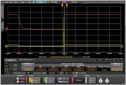
current, with a current value of zero. This operation is depicted in Figure 4,
using a Keysight N6781A 2-quadrant SMU module designed for testing battery
powered devices, operating within an N6705B DC Power Analyzer. In this example
the current ARB for the dropout was both programmed and the results shown in
Figure 1 captured using the companion 14585A software.
Figure 1: Current ARB creates a high impedance dropout to
simulate battery contact bounce
Another caveat with using this approach for simulating
battery contact bounce is paying careful attention to the behavior of the mode
crossovers. For the first crossover, from voltage limit to constant current
operation (at zero current) there is a small amount of lag time, typically just
a fraction of a millisecond, before the transition happens. This becomes more
significant only when trying to simulate extremely short contact bounce
periods. More important is when crossing back over from constant zero current
back to voltage limit operation. There is a short period when the current goes
up to its high level before the voltage limit gains control, holding the
voltage at the battery’s voltage level. Usually any capacitance at the input of
the DUT will normally absorb any short spike of current. If this crossover is
slow enough, and there is very little or no capacitance, the device could see a
voltage spike. The N6781A has very fast responding circuits however, minimizing
crossover time and inducing just 250 mV of overshoot, as is seen in Figure 1.
Hopefully, now armed with all of these details, you will
be able to select an approach that works best for you for simulating battery
contact bounce!
