Showing posts with label programming speed. Show all posts

Monday, August 31, 2015

What is meant by a “fast” power supply?

We regularly get requests for a power supply with a “fast” output. This means different things to different people, so we always have to ask clarifying questions. Not only do we need to find out what change needs to happen quickly, but we need to quantify the need and find out how quickly it needs to change. For example, recently, a customer testing power amplifiers wanted to know how quickly a particular power supply could attain its output voltage. Two ways to look at this are:

1. How long does it take for a power supply output voltage to change from one value to another value?
2. How long does it take for a power supply output voltage to recover to its original value following a load current change?

This customer wanted to know the answer to question 1. Luckily, both of these answers can be found in our specifications and supplemental characteristic tables.

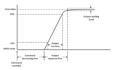
Question 1 is referring to a supplemental characteristic that has a variety of similar names: programming speed, settling time, output response time, output response characteristic, and programming response time. This is typically described with rise time and fall time values, or settling time values, or occasionally with a time constant. Rise (and fall) time values are what you would expect: the time it takes for the output voltage to go from 10% of its final value to 90% of its final value. Settling time (labeled “Output response time” in the graph below) is the time from when the output voltage begins to change until it settles within a specified settling band around the final value, such as 1% or even 0.1%, or sometimes within an LSB (least significant bit) of the final value. My fellow blogger, Ed, posted about how this affects throughput (click here) back in September of 2013.

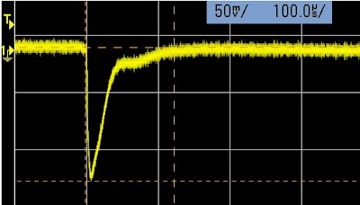
Question 2 is referring to a specification called transient response, or load transient recovery time. Whenever the load current changes from a low current to a higher current, the output voltage temporarily dips down slightly and then quickly recovers back to the original value (or close to it).
The feedback loop design inside the power supply determines how quickly the voltage recovers from this load current change. Higher bandwidth designs recover more quickly but are less stable. Likewise, lower bandwidth designs recover more slowly and are more stable. Ed posted about optimizing the output response back in April of this year (click here).

So the transient response recovery time is the time from when the load current begins to increase (coincident with the output voltage beginning to drop) to when the output voltage settles within a specified settling band around the final voltage value.

Our customer was interested in a “fast” power supply, meaning one with a settling time to meet his needs. Once we understood what he needed, we directed him to a power supply that could easily meet his requirements!


Monday, April 28, 2014

Upcoming Seminar on Using Your Power Supply to Improve Test Throughput

I have provided here on “Watt’s up?” a number of ideas on how you can improve your test throughput from time to time, as it relates on how to make better use of you system power supplies to accomplish this. I have categorized these ideas on how to improve throughput as either fundamental or advanced.

In “How fundamental features of power supplies impact your test throughput” (click here to review) I shared in a two-part posting definitions of key fundamental power supply features that impact test throughput and ways to make improvements to literally shave seconds off of your test time.

One example (of several) of an advanced idea on improving throughput I previously shared here is “Using the power supply status system to improve test throughput” (click here to review). Here I explain how, by monitoring the status system, you can improve throughput by not relying on using excessively long fixed wait statements in your programming.

I hope you have found these ideas helpful. If you would like to learn more about using your system power supply to improve your test throughput I will be presenting a live web-based seminar this week, in just a couple of days, April 30th, at 1:00 PM EST on this very topic!

In this seminar I will go through a number of things I’ve shared here on “Watt’s up?” in the past, but in greater detail. In addition, I have also prepared several new ideas as well in this seminar that you might find of help for your particular test situation.  You can register online at the following (click here to access seminar description and registration).  In case you miss the live event I expect you will be able to register and listen to seminar afterward as well, as it will be recorded.

So if improving your test throughput is important to you I hope you are able to attend the seminar!


Wednesday, October 9, 2013

Using the power supply status subsystem to improve your test throughput

Continuing on my throughput theme here, one recommendation is to take advantage of the power supply’s status subsystem. Some power supply operations take notably longer than most to complete than others. Two notable examples:
  • Initializing a triggered measurement
  • Initializing a triggered output transient or output list event

When developing programs you can include long, fixed wait statements to make certain these operations have completed before proceeding. However, this can easily add many tens of milliseconds or more of unnecessary waiting, increasing overall test time.  A better way is to take advantage of the DC power supply’s status subsystem features that eliminate unnecessary waiting for these operations.

Triggered measurement and output sourcing events can substantially speed up testing by providing actions tightly synchronized with other test activities. But they do have some up-front set up overhead time needed for initializing them. Instead of using a fixed programming delay following an initialization operation it is better to take advantage of the Operation Status Group register in the status subsystem, which is illustrated in Figure 1.


Figure 1: Agilent N6700 series DC power system operation status group

The “WTG meas” bit (#3) or “WTG trans bit (#4) in the condition register can be monitored with a loop in the test program to see when they turn true. At the moment the measurement or output sourcing event is initiated and ready for a trigger the test program will then proceed with its execution without incurring any unnecessary additional waiting. This saves a considerable amount of time as illustrated in Figure 2.


Figure 2: Operation-complete wait time distribution

Instead of waiting for the full worst-case each and every time, the wait is now just the actual time. When repeated over and over for all DUTs being tested, the net result is the average of the actual wait time, which in most cases is just a small fraction of the worst case time! The net result can be many tens of milliseconds test time savings, making an improvement in test throughput.

The first five hints of my compendium “10 Hints for Improving Throughput with your Power Supply” can be viewed here: (click here to access).  For those reading our “Watt’s Up?” blog here are getting the opportunity to preview one of the remaining 5 hints yet to be released!

Thursday, September 12, 2013

How fundamental features of power supplies impact your test throughput – Part 2

In part 1 of” How fundamental features of DC power supplies impact your test throughput” (click here to access) I shared definitions of some of the fundamental power supply features that impact test throughput, including:
  • Command processing time
  • Up-programming response time
  • Down-programming response time


Another fundamental DC power supply feature impacting test throughput is its measurement time. There are actually two aspects to a DC power supply’s measurement time as depicted in Figure 1:
  • Measurement settling time
  • Measurement integration time


Figure 1: DC power supply measurement time

A good indicator of a DC power supply having a high performance measurement system is having programmable measurement integration time, or aperture time, often programmed in power line cycles (PLCs).  One reason for having a programmable integration time is for minimizing any 50 or 60 Hz AC line ripple getting into the DC measurement, by setting the time one or more multiples of a PLC.  Setting the time to 1 PLC provides good ripple rejection with relatively good throughput. When AC line ripple is not an issue the integration time can be set even smaller than 1 PLC, further reducing measurement time. When the DC power supply has a programmable measurement integration time it will no doubt also have a fast-responding measurement system as well, typically just milliseconds, to complement the higher achievable throughput with programmable measurement integration time.

In comparison basic DC power supplies commonly use a 100 millisecond fixed integration time to support AC ripple rejection for both 50 and 60 Hz line frequencies. They also have low bandwidth, slow-responding measurement systems, which can long time to settle after any step change in loading, before a valid measurement can be taken.

We have just introduced our Advanced Power System (APS) DC power supplies. This is a family of high-performance, high power (1 and 2 kW) DC power supplies designed to address the most demanding test challenges. These fundamental throughput-related features for APS are typically more than two orders of magnitude faster compared to more basic-performance DC power supplies, providing much better throughput in manufacturing test. A colleague of mine recently posted details of their introduction on his “General Purpose Electronic Test Equipment (GEPETE)” blog (click here to access) which I believe you will find of interest. Included in this introduction is a link on throughput that takes you to a series of application briefs I have written that go into more detail on improving test throughput with the DC power supply, which you may find very useful.


So how much test throughput improvement might you expect to see by switching from a basic-performance DC source to a high-performance DC source? Well, it really depends on how much the testing makes use of the DC power supply. If it only uses the power supply to provide a fixed DC bias to the device under test (DUT) that never changes for the duration of the test then it will not make a significant difference. More often than not however, a DUT is tested at several bias voltages with several current drain measurements taken for the various bias voltage settings and DUT operating modes. This can add up to a considerable amount of test time. In this case a high-performance DC power supply can more than pay for itself many times over due to improved test throughput.  To get an idea of the kind of difference a high-performance DC power supply can make I set up a representative benchmark test It compares the throughput performance one of our new APS DC power supplies to that of a more basic-performance power supply.  If you are interested in finding out how much difference it made, I made a video of this benchmark testing, entitled “Increasing Test Throughput with Advanced Power System” (click here to access). All I am going to say here is it is an impressive difference but you will need to watch the video to see how much difference!

Friday, September 6, 2013

How fundamental features of power supplies impact your test throughput – Part 1

When it comes to manufacturing of electronic products, reducing test time to improve throughput is virtually always a top priority, because “time is money” as the old saying goes! Usually most all of the attention may be placed on reducing the test time of the banner aspects of the product, such as the RF performance of a wireless device, for example. However, the choice of the DC system power supply can also have a huge impact on your test time and throughput during manufacturing. You may find the lowest cost, more basic-performance DC power supply that meets your immediate needs end up costing you the difference in price many, many times over of that of a higher-performance DC power supply having better throughput performance in the long run!

The DC power supply can incorporate a number of advanced features, such as elaborate triggering and sequencing systems, which will allow you restructure your testing to optimize throughput. However, even fundamental throughput-related features of the power supply can also have a large impact on your test time, including:
  • Command processing time
  • Output up-programming time
  • Output down-programming time
  • Measurement time

Figure 1 illustrates what the command processing and up-programming times are for a DC power supply. The command processing time is the time from when the command is first received to the point where the power supply starts acting on it. In this case it is when power supply’s output starts to change. The up-programming response time is the time the power supply takes for the output to rise and settle within a small band around the final output level, after processing the command instructing it to change its output level.


Figure 1: Power supply command processing and up-programming response times

The down-programming response time is like the up-programming response time except that the power supply is instead being programmed to a lower level. However, you need to look at down-programming independently as short up-programming time does not necessarily guarantee comparably short down-programming time. More basic performance DC power supplies usually lack an active down-programmer circuit that quickly brings down the output. In this case the down-programming response time can be very dependent on how much load the DUT presents to the power supply’s output.

How much difference is there in performance between more basic performance and higher performance DC power supplies on these throughput-related features? It can be considerable; over several orders of magnitude difference. As one example, command processing time can range from up to 100’s of milliseconds for entry-level power supplies to under 1 millisecond for high performance power supplies.
Another fundamental throughput-related feature of a DC power supply is its measurement time. There are a couple of aspects to consider here as well, which I will elaborate on in part 2 of this series on how fundamental features of power supplies impact your test throughput, in an upcoming posting here on “Watt’s Up?” along with tying it all together to show how they affect actual test throughput!

Tuesday, June 25, 2013

Current limit setting affects voltage response time

The current limit setting in a power supply is primarily used to protect the device under test (DUT) from excessive current. You should set your current limit setting higher than the maximum amount of current you expect your DUT to draw, but low enough so that if your DUT fails as a short or low impedance, it does not draw an amount of current that can damage wires, connectors, or the DUT itself due to excessive current. The power supply will limit the current at the current limit setting and reduce the voltage accordingly. If you want, you can turn on over-current protection (OCP) and then the power supply output will turn off if the output transitions into constant current (CC) mode. For previous posts on this topic, click here and here.

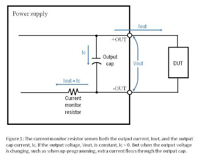
Current limit plays an important role in protecting your DUT. But you should also know that the current limit setting can affect the voltage response time, specifically the up-programming speed. Voltage up-programming speed is the time it takes the output voltage to go from a lower voltage to a higher voltage. For example, the up-programming output response time for an Agilent N5768A power supply (rated for 80 V, 19 A, 1520 W) is specified to be no more than 150 ms with a full load (settling band is 1% of the rated output voltage). This spec assumes the current limit is set high enough to not limit the current. The output capacitor of this power supply will draw current as the voltage on the cap rises (Ic = C * dVc/dt). The output current and the cap current flow through the current monitoring resistor which is where the current is measured and compared to the current limit setting. See Figure 1. Therefore, the output cap current adds to the output current and can cause the power supply to momentarily go into CC mode as the output cap charges. If this happens, the output voltage will rise more slowly than if the power supply stayed in constant voltage (CV) mode the entire time the output voltage was rising and charging the output cap.

So, the current limit setting can slow down the voltage response time if set too low causing the power supply to momentarily go into CC mode as the output voltage is rising and the output cap is charging. This effect is shown in Figure 2 for various current limit settings on the N5768A power supply. As you can see, the lower the current limit setting (Iset), the longer it takes for the voltage to reach its final value.


If fast up-programming response time is important to you in your power supply application, make sure you set your current limit high enough to provide current to your DUT and to charge the power supply’s output capacitor without going into CC mode. Once the output voltage reaches its final value, you can always lower the current limit again to properly protect your DUT.