Showing posts with label two quadrant. Show all posts

Wednesday, September 17, 2014

Simulating battery contact bounce, part 1

One test commonly done during design validation of handheld battery powered devices is to evaluate their ability to withstand a short loss of battery power due to being bumped and the contacts momentarily bouncing open, and either remain operating or have sufficient time to handle a shutdown gracefully. The duration of a contact bounce can typically range anywhere from under a millisecond to up to 100 milliseconds long.

To simulate battery contact bouncing one may consider programming a voltage drop out on a reasonably fast power supply with arbitrary 
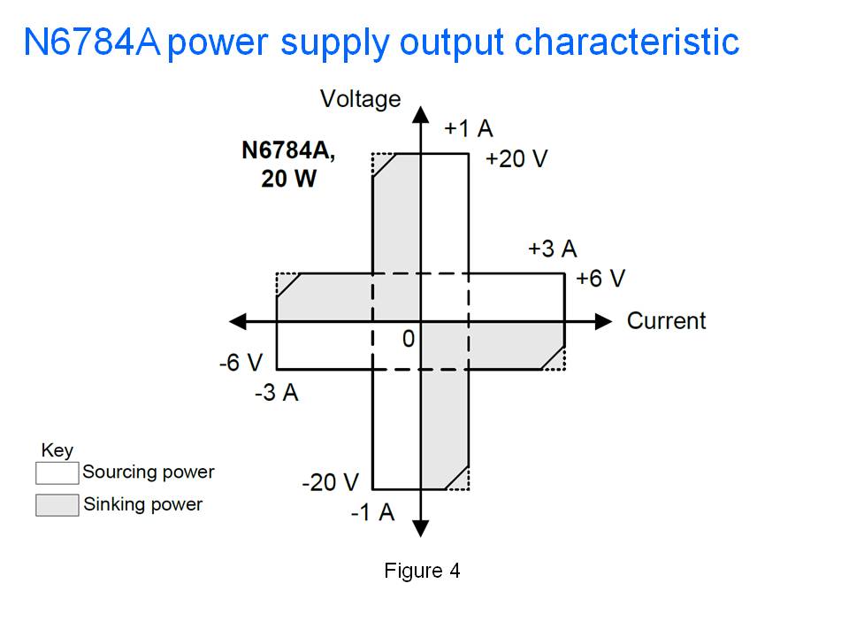
waveform capabilities, like several of the N675xA, N676xA, or N678xA series modules used in the N6700 series Modular DC Power System or N6705B DC Power Analyzer mainframe, shown in Figure 1. It is a simple matter to program a voltage dropout of specified duration. As an example a voltage dropout was programmed in Figure 2 on an N6781A SMU module using the companion 14585A software.


 Figure 1: N6700 series and N6705B mainframes and modules


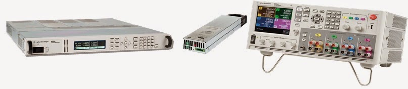
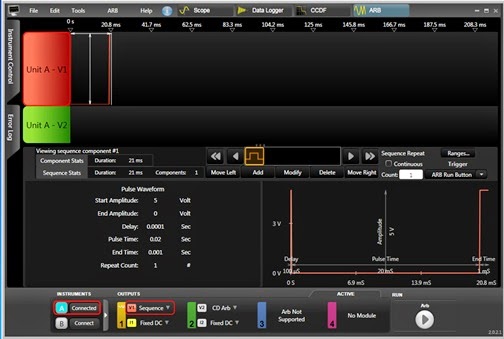
Figure 2: Programming a voltage drop out using the N6705B and N6781A SMU module

While a voltage dropout is fine for many applications, like automotive, in many situations it does not work well for simulating battery contact bounce. The reason for this is there is one key difference to note about a voltage dropout versus a battery contact bounce. During a voltage dropout the source impedance remains low. During a battery contact bounce the source impedance is an open circuit. However, a DC source having the ability to generate a fast voltage dropout is a result of it being able to pull its output voltage down quickly. This is due to its ability to sink current as well as source current. The problem with this is, for many battery powered devices, this effectively short-circuits the battery input terminals, more than likely causing the device to instantly shut down by discharging any carry-over storage 
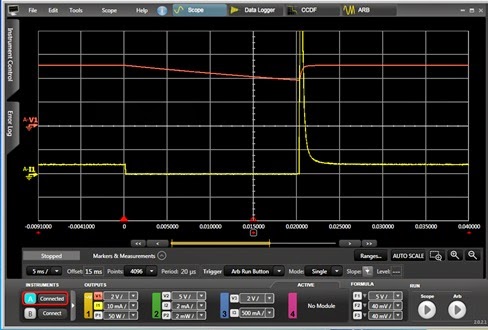
and/or disrupting the battery power management system. As one example consider a mobile device having 50 microfarads of input capacitance and draws 4 milliamps of standby current. This capacitance would provide more than adequate 
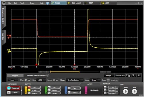
carryover for a 20 millisecond battery contact bounce. However, if a voltage dropout is used to simulate battery contact bounce, it immediately discharges the mobile device’s input capacitance and pulls the battery input voltage down to zero, as shown by the red voltage trace in Figure 3. The yellow trace is the corresponding current drain. Note the large peaks of current drawn that discharge and recharge the DUT’s input capacitor.


 Figure 3: Voltage dropout applied to DUT immediately pulls voltage down to zero

One effective solution for preventing the DC source from shorting out the battery input is to add a DC blocking diode in series with the battery input, so that current cannot flow back out, creating high impedance during the dropout. This is illustrated in Figure 4.


Figure 4: Blocking diode added between SMU and DUT

One thing to note here is the diode’s forward voltage drop needs to be compensated for. Usually the best way to do this just program the DC source with the additional voltage needed to offset the diode’s voltage drop. The result of this is shown in Figure 5. As shown by the red trace the voltage holds up relatively well during the contact bounce period. Because the N6781A SMU has an auxiliary voltage measurement input it is able to directly measure the voltage at the DUT, on the other side of the blocking diode, instead of the output voltage of the N6781A. As seen by the yellow current trace there is no longer a large peak of current discharging the capacitor due to the action of the blocking diode.


 Figure 5: Blocking diode prevents voltage dropout from discharging DUT 

Now you should have a much better appreciation of the differences between creating a voltage dropout and simulating battery contact bounce! And as can be seen a blocking diode is a rather effective means of simulating battery contact bounce using a voltage dropout. Stay tuned for my second part on additional ways of simulating battery contact bounce on an upcoming posting.
.


Tuesday, June 3, 2014

Upcoming Webinar on High Power Source/Sink Solutions for Testing Bidirectional Energy Devices

Bidirectional and regenerative energy devices both source and sink power and energy. Correspondingly, a solution that can both source and sink power and energy is needed for properly testing them. In the past here on “Watt’s up?” we have talked about what two and four quadrant operation is in our posting “What is bipolar four quadrant power? (Click here to review). We have also talked about cross over behavior between sourcing and sinking current with a DC source that will operate in two quadrants in a two-part posting  “Power supply current source-to-sink crossover characteristics” (Click here to review pt. 1) and (Click here to review pt. 2). These give useful insights about the nature of multi-quadrant solutions for bi-directional test applications.


Figure 1: The four operating quadrants

Bidirectional and regenerative energy devices that are used in many applications, such as satellite power systems, alternative energy, automotive, and many other areas, operate at kilowatt and higher power levels. These higher power levels have a significant impact on solutions and approaches taken to address their testing.  Also, the nature of these bidirectional and regenerative energy devices are not all the same. This also has an impact in that the capabilities of the test solutions need to be different to address these different types of devices.

In my upcoming webinar on June 18th, titled “Conquering the High Power Source/Sink Test Challenge” I will be exploring the test needs of key bidirectional and regenerative energy devices and then go into the details of various test solutions and approaches for sourcing and sinking power and energy, along with their associated advantages and disadvantages. This is just a couple of weeks away. So if you are involved in this kind of work and are interested, or would just like to learn more, you can register online at the following (click here).  In case you cannot join the live event you will still be able to register and listen to seminar afterward instead, as it will be recorded.  I hope you can join in!


.

Friday, December 21, 2012

Two-quadrant power supplies are better than one!

Back in October, I posted an explanation about what was a bipolar (four-quadrant) power supply (see post here: http://powersupplyblog.tm.agilent.com/2012/10/what-is-bipolar-four-quadrant-power.html). That post covered two-quadrant supplies as well. Last week, while in Lorton, Virginia, I had an opportunity to meet with some of our U.S. Army customers  - engineers working at Fort Belvoir. Many of the engineers worked in the Counter Measures Research Laboratory (CMRL). While they are very careful to not reveal any details about the specifics of the work they do, one of the engineers shared a story with me about two-quadrant operation that is worth repeating.

The story was told while I was providing a demonstration of one of our power supplies, the N6705B DC Power Analyzer (see Figure 1). I was explaining to a group of engineers that some of the 34 power modules that can be installed in the N6705B are two-quadrant power supplies: they can source current and also sink current at one voltage polarity. Other power modules are four-quadrant power supplies: they can source and sink current, and provide positive or negative voltage. This explanation inspired one of the engineers to tell the group that the N6705B helped him solve a problem!


A battery operated device (he did not mention what it was) came into his lab because it was not functioning properly: it had some type of intermittent problem. In an attempt to reproduce the problem, he removed the battery and connected the device’s power input terminals to a power supply on his lab bench. But even after running the device for long periods of time and through all of its operating modes, he was unable to reproduce the intermittent problem.

One of his colleagues suggested he try connecting the device to a two-quadrant power supply installed in the N6705B they owned. The original power supply he was using was a one-quadrant supply – it could source power, but could not absorb power. The battery that normally powers the device can source and sink (absorb) power, so perhaps a power supply that more closely mimicked the behavior of the battery could help uncover the problem. Well, this worked! With the device connected to the two-quadrant power supply in the N6705B, the intermittent problem showed up again proving that it was related to the battery being able to source and sink power – a power supply with similar characteristics was needed. Apparently, the device has a mode in which it momentarily forces current back out of the battery input terminals. That current is normally absorbed by the battery. And during that time, this intermittent problem must show up. During test, a single-quadrant power supply is unable to absorb the power and therefore does not reveal the problem. A two-quadrant power supply can sink the momentary current, and the problem was back, enabling the engineer to track it down and eliminate it! See Figure 2 for an example of the output characteristic of a two-quadrant power supply.

This example demonstrates the importance of choosing a power supply with the right output characteristics for your test. When testing a device or circuit with a power supply, the closer that power supply’s behavior is to the actual power used with the device or circuit, the more you will reveal about the actual performance of your device or circuit.  There are applications in which a two-quadrant power supply will better replicate a battery’s behavior than a single-quadrant power supply, even if you don’t expect the battery to absorb power during test. One CMRL engineer experienced this firsthand.

Monday, December 10, 2012

More on power supply current source-to-sink crossover characteristics


On my earlier posting “Power supply current source-to-sink crossover characteristics” I showed what the effects on the output voltage of a unipolar two-quadrant-power supply were, resulting from the output current on the power supply transitioning between sourcing and sinking. In that example scenario, the power supply was maintaining a constant output voltage and the transitioning between sourcing and sinking current was dictated by the external device connected to and being powered by the power supply. This is perhaps the most common scenario one will encounter that will drive the power supply between sourcing current and sinking current.

Other scenarios do exist that will drive a unipolar two-quadrant power supply to transition between sourcing and sinking output current. One scenario is nearly identical to the earlier posting. However, instead of the device transitioning its voltage between being less and greater than the power supply powering it, the power supply instead transitions its voltage between being less and greater than the active device being normally powered.  A set up for evaluating this scenario on an Agilent N6781A two-quadrant DC source is depicted in Figure 1.


Figure 1: Evaluating current source-to-sink crossover on an N6781A operating in constant voltage

In this scenario having the DC source operating as a voltage source and transitioning between 1.5 and 4.5 volts causes the current to transition between -0.75 and +0.75A.  The voltage and current waveforms captured on an oscilloscope are shown in Figure 2.


Figure 2: Voltage and current waveforms for the set up in Figure 1

The waveforms in Figure 2 are as what should be expected. The actual transition points are where the current waveform passes through zero on the rising and falling edge. An expanded view to the current source-to-sink transition is shown in Figure 3.


Figure 3: Expanded voltage and current waveforms for the set up in Figure 1

As can be seen the voltage ramp transitions smoothly at the threshold point, or zero crossing point, of the current waveform. The reason being is that the DC is maintaining its operation as a voltage source. Its voltage feedback loop is always in control.


Yet one more scenario that will drive a unipolar two-quadrant source to transition between sourcing and sinking current is operate it as a current source and program is current setting between positive and negative values. In this case the device under test that was used is a voltage source.  One real-world example is cycling a rechargeable battery by alternately applying charging and discharging currents to it. The set up for evaluating this scenario, again using an N6781A two-quadrant DC source is depicted in Figure 4.


Figure 4: Evaluating current source-to-sink crossover on an N6781A operating in constant current

For Figure 4 the N6781A was set to operate in constant current and programmed to alternately transition between -0.75A and +0.75A current settings. The resulting voltage and current waveforms are shown in Figure 5.


Figure 5: Voltage and current waveforms for the set up in Figure 4

The waveforms in Figure 5 are as what should be expected. The actual transition points are where the current waveform passes through zero on the rising and falling edge. An expanded view to the current source-to-sink transition is shown in Figure 6.


Figure 6: Expanded voltage and current waveforms for the set up in Figure 4

As the N6781A is operating in current priority the interest is in how well it controls its current while transitioning through the zero-crossing point. As observed in Figure 6 it transitions smoothly through the zero-crossing point. The voltage performance is determined by the DUT, not the N6781A, as the N6781A is operating in constant current.

So what was found here is, for a unipolar two-quadrant DC source, transitioning between sourcing and sinking current should generally be virtually seamless as, under normal circumstances, should remain in either constant voltage or constant current during the entire transition.

Wednesday, December 5, 2012

Power supply current source-to-sink crossover characteristics


A two-quadrant power supply is traditionally one that outputs unipolar voltage but is able to both source as well as sink current. For a positive polarity power source, when sourcing current it is operating in quadrant 1 as a conventional power source. When sinking current it is operating in quadrant 2 as an electronic load. Conversely, a negative polarity two-quadrant  power source operates in quadrants three and four. Further details on power supply operating quadrants are provided in a recent posting here in ‘Watt’s Up?”, What is a bipolar (four-quadrant) power supply? Often a number of questions come up when explaining two-quadrant power supply operation, including:
  • What does it take to get the power supply operating as a voltage source to cross over from sourcing to sinking current?
  • What effect does crossing over from sourcing to sinking current have on the power supply’s output?


For a two-quadrant voltage source to be able to operate in the second quadrant as an electronic load, the device it is normally powering must also be able to source current and power as well as normally draw current and power. Such an arrangement is depicted in Figure 1, where the device is normally a load, represented by a resistance, but also has a charging circuit, represented by a switch and a voltage source with current-limiting series resistance.


Figure 1: Voltage source and example load device arrangement for two-quadrant operation.

There is no particular control on a two-quadrant power supply that one has to change to get it to transition from sourcing current and power to sinking current and power from the device it is normally powering. It is simply when the source voltage is greater than the device’s voltage then the voltage source will be operating in quadrant one sourcing power and when the source voltage is less than the device’s voltage the voltage source will be operating in quadrant two as an electronic load. In figure 1, during charging the load device can source current back out of its input power terminals as long as the charger’s current-limited voltage is greater than the source voltage.

It is assumed that load device’s load and charge currents are lower than the positive and negative current limits of the voltage source so that the voltage source always remains in constant voltage (CV) operation. A step change in current is the most demanding from a transient standpoint, but as the voltage source is always in its constant voltage mode it handle the transition well as its voltage control amplifier is always in control. This is in stark contrast to a mode cross over between voltage and current where different control amplifiers need to exchange control of the power supply’s output. In this later case there can be a large transient while changing modes. See another posting, Why Does My Power Supply Overshoot at Current Limit? Insights on Mode Crossover” for further information on this.  There is a specification given on voltage sources which quantifies the impact one should expect to see from a step change in current going from sourcing current to sinking current, which is its transient voltage response.  A transient voltage response measurement was taken on an N6781A two-quadrant DC source, stepping the load from 0.1 amps to 1.5 amps, roughly 50% of its rated output current.


Figure 2: Agilent N6781A transient voltage response measurement for 0.1A to 1.5A load step

However, the transient voltage response shown in Figure 2 was just for sourcing current. With a well-designed two-quadrant voltage source the transient voltage response should be virtually unchanged for any step change in current load, as long as it falls within the voltage source’s current range.  The transient voltage response for an N6781A was again capture in Figure 3, but now for stepping the load between -0.7A and +0.7A.


Figure 3: Agilent N6781A transient voltage response measurement for -0.7A to +0.7A load step

As can be seen in Figures 2 and 3 the voltage transient response for the N6781A remained unchanged regardless of whether the stepped load current was all positive or swung between positive and negative (sourcing and sinking).

While the transient voltage response addresses the dynamic current loading on the voltage source there is another specification that addresses the static current loading characteristic, which is the DC load regulation or load effect.  This is a very small effect on the order of 0.01% output change for many voltage sources. For example, for the N6781A the load effect in its 6 volt range is 400 microvolts for any load change. In the case of the N6781A being tested here the DC change was the same for both the 0.1 to 1.5 amp step and the -0.7 to +0.7 amp step change.


There are two more scenarios which will cause a two-quadrant power supply transition between current sourcing and sinking.  The first is very similar to above with the two-quadrant power supply operating in constant voltage (CV) mode, but instead of the DUT changing, the power supply changes its voltage level instead.  The final scenario is having the two-quadrant power supply operating in constant current with the DUT being a suitable voltage source that is able to source and sink power as well, like a battery for example. Here the two-quadrant power supply can be programmed to change from a positive current setting to a negative current setting, thus transitioning between sourcing and sinking current again, and its current regulating performance is now a consideration.  Both good topics for future postings!

Friday, October 26, 2012

What is a bipolar (four-quadrant) power supply?

To answer this question, I have to start with a basic definition of polarity conventions. Figure 1 shows a simple diagram of a power supply (a two-terminal device) with the standard polarity for voltage and current. A standard power supply typically is a source of power. To source power, current must flow out of the positive voltage terminal. Most power supplies source energy in this way by providing a positive output voltage and positive output current. This is known as a uni-polar power supply because it provides voltage with only one polarity. By convention, the “polarity” nomenclature typically refers to the polarity of the voltage (not the direction of current flow).
If current flows into the positive voltage terminal, the power supply is sinking current and is acting like an electronic load – it is absorbing and dissipating power instead of sourcing power. Most power supplies do not do this although many Agilent power supplies can sink some current to quickly pull down their output voltage when needed – this is known as a down-programmer capability – see this post for more info: http://powersupplyblog.tm.agilent.com/2012/03/if-you-need-fast-rise-and-fall-times.html.

To fully define power supply output voltage and current conventions, a Cartesian coordinate system is used. The Cartesian coordinate system simply shows two parameters on perpendicular axes. See Figure 2.  By convention, the four quadrants of the coordinate system are defined as shown. Roman numerals are typically used to refer to the quadrants. For power supplies, voltage is normally shown on the vertical axis and current on the horizontal axis. This coordinate system is used to define the valid operating points for a given power supply. A graph of the boundary surrounding these valid operating points on the coordinate system is known as the power supply’s output characteristic.
As mentioned earlier, some power supplies are uni-polar (produce only a single polarity output voltage), but can source and sink current. These power supplies can operate in quadrants 1 and 2 and can therefore be called two-quadrant supplies. In quadrant 1, the power supply would be sourcing power with current flowing out of the more positive voltage terminal. In quadrant 2, the power supply would be consuming power (sinking current) with current flowing into the more positive voltage terminal.

Some power supplies can provide positive or negative voltages across their output terminals without having to switch the external wiring to the terminals. These supplies can typically operate in all four quadrants and are therefore known as four-quadrant power supplies. Another name for these is bipolar since they are able to produce either positive or negative voltage on their output terminals. In quadrants 1 and 3, a bipolar supply is sourcing power: current flows out of the more positive voltage terminal. In quadrants 2 and 4, a bipolar supply is consuming power: current flows into the more positive voltage terminal. See Figure 3.
Agilent’s N6784A is an example of a bipolar power supply. It can source or sink current and the output voltage across its output terminals can be set positive or negative. It is a 20 W Source/Measure Unit (SMU) with multiple output ranges. See Figure 4 for the output characteristic of the N6784A.
To summarize, a bipolar or four-quadrant power supply is a supply that can provide positive or negative output voltage, and can source or sink current. It can operate in any of the four quadrants of the voltage-current coordinate system.