Showing posts with label voltage limit. Show all posts

Wednesday, December 5, 2012

Power supply current source-to-sink crossover characteristics


A two-quadrant power supply is traditionally one that outputs unipolar voltage but is able to both source as well as sink current. For a positive polarity power source, when sourcing current it is operating in quadrant 1 as a conventional power source. When sinking current it is operating in quadrant 2 as an electronic load. Conversely, a negative polarity two-quadrant  power source operates in quadrants three and four. Further details on power supply operating quadrants are provided in a recent posting here in ‘Watt’s Up?”, What is a bipolar (four-quadrant) power supply? Often a number of questions come up when explaining two-quadrant power supply operation, including:
  • What does it take to get the power supply operating as a voltage source to cross over from sourcing to sinking current?
  • What effect does crossing over from sourcing to sinking current have on the power supply’s output?


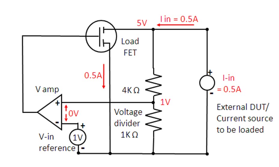
For a two-quadrant voltage source to be able to operate in the second quadrant as an electronic load, the device it is normally powering must also be able to source current and power as well as normally draw current and power. Such an arrangement is depicted in Figure 1, where the device is normally a load, represented by a resistance, but also has a charging circuit, represented by a switch and a voltage source with current-limiting series resistance.


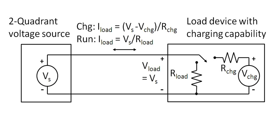
Figure 1: Voltage source and example load device arrangement for two-quadrant operation.

There is no particular control on a two-quadrant power supply that one has to change to get it to transition from sourcing current and power to sinking current and power from the device it is normally powering. It is simply when the source voltage is greater than the device’s voltage then the voltage source will be operating in quadrant one sourcing power and when the source voltage is less than the device’s voltage the voltage source will be operating in quadrant two as an electronic load. In figure 1, during charging the load device can source current back out of its input power terminals as long as the charger’s current-limited voltage is greater than the source voltage.

It is assumed that load device’s load and charge currents are lower than the positive and negative current limits of the voltage source so that the voltage source always remains in constant voltage (CV) operation. A step change in current is the most demanding from a transient standpoint, but as the voltage source is always in its constant voltage mode it handle the transition well as its voltage control amplifier is always in control. This is in stark contrast to a mode cross over between voltage and current where different control amplifiers need to exchange control of the power supply’s output. In this later case there can be a large transient while changing modes. See another posting, Why Does My Power Supply Overshoot at Current Limit? Insights on Mode Crossover” for further information on this.  There is a specification given on voltage sources which quantifies the impact one should expect to see from a step change in current going from sourcing current to sinking current, which is its transient voltage response.  A transient voltage response measurement was taken on an N6781A two-quadrant DC source, stepping the load from 0.1 amps to 1.5 amps, roughly 50% of its rated output current.


Figure 2: Agilent N6781A transient voltage response measurement for 0.1A to 1.5A load step

However, the transient voltage response shown in Figure 2 was just for sourcing current. With a well-designed two-quadrant voltage source the transient voltage response should be virtually unchanged for any step change in current load, as long as it falls within the voltage source’s current range.  The transient voltage response for an N6781A was again capture in Figure 3, but now for stepping the load between -0.7A and +0.7A.


Figure 3: Agilent N6781A transient voltage response measurement for -0.7A to +0.7A load step

As can be seen in Figures 2 and 3 the voltage transient response for the N6781A remained unchanged regardless of whether the stepped load current was all positive or swung between positive and negative (sourcing and sinking).

While the transient voltage response addresses the dynamic current loading on the voltage source there is another specification that addresses the static current loading characteristic, which is the DC load regulation or load effect.  This is a very small effect on the order of 0.01% output change for many voltage sources. For example, for the N6781A the load effect in its 6 volt range is 400 microvolts for any load change. In the case of the N6781A being tested here the DC change was the same for both the 0.1 to 1.5 amp step and the -0.7 to +0.7 amp step change.


There are two more scenarios which will cause a two-quadrant power supply transition between current sourcing and sinking.  The first is very similar to above with the two-quadrant power supply operating in constant voltage (CV) mode, but instead of the DUT changing, the power supply changes its voltage level instead.  The final scenario is having the two-quadrant power supply operating in constant current with the DUT being a suitable voltage source that is able to source and sink power as well, like a battery for example. Here the two-quadrant power supply can be programmed to change from a positive current setting to a negative current setting, thus transitioning between sourcing and sinking current again, and its current regulating performance is now a consideration.  Both good topics for future postings!

Tuesday, August 7, 2012

How Does an Electronic Load Regulate It’s Input Voltage, Current, and Resistance?


In a sense electronic loads are the antithesis of power supplies, i.e. they sink or absorb power while power supplies source power. In another sense they are very similar in the way they regulate constant voltage (CV) or constant current (CC). When used to load a DUT, which inevitably is some form of power source, conventional practice is to use CC loading for devices that are by nature voltage sources and conversely use CV loading for devices that are by nature current sources. However most all electronic loads also feature constant resistance (CR) operation as well. Many real-world loads are resistive by nature and hence it is often useful to test power sources meant to drive such devices with an electronic load operating in CR mode.

To understand how CC and CV modes work in an electronic load it is useful to first review a previous posting I wrote here, entitled “How Does a Power Supply Regulate It’s Output Voltage and Current?”. Again, the CC and CV modes are very similar in operation for both a power supply and an electronic load. An electronic load CC mode operation is depicted in Figure 1.


Figure 1: Electronic load circuit, constant current (CC) operation

The load, operating in CC mode, is loading the output of an external voltage source. The current amplifier is regulating the electronic load’s input current by comparing the voltage on the current shunt against a reference voltage, which in turn is regulating how hard to turn on the load FET. The corresponding I-V diagram for this CC mode operation is shown in Figure 2. The operating point is where the output voltage characteristic of the DUT voltage source characteristic intersects the input constant current load line of the electronic load.


Figure 2: Electronic load I-V diagram, constant current (CC) operation

CV mode is very similar to CC mode operation, as depicted in Figure 3.  However, instead of monitoring the input current with a shunt voltage, a voltage control amplifier compares the load’s input voltage, usually through a voltage divider, against a reference voltage. When the input voltage signal reaches the reference voltage value the voltage amplifier turns the load FET on as much as needed to clamp the voltage to the set level.


Figure 3: Electronic load circuit, constant voltage (CV) operation

A battery being charged is a real-world example of a CV load, charged typically by a constant current source. The corresponding I-V diagram for CV mode operation is depicted in figure 4.


Figure 4: Electronic load I-V diagram, constant voltage (CV) operation

But how does an electronic load’s CR mode work? This requires yet another configuration, as depicted in figure 5. While CC and CV modes compare current and voltage against a reference value, in CR mode the control amplifier compares the input voltage against the input current so that one is the ratio of the other, now regulating the input at a constant resistance value.  With current sensing at 1 V/A and voltage sensing at 0.2 V/V, the electronic load’s resulting  input resistance value is 5 ohms for its CR mode operation in Figure 5.


Figure 5: Electronic load circuit, constant resistance (CR) operation

An electronic load’s CR mode is well suited for loading a power source that is either a voltage or current source by nature. The corresponding I-V diagram for this CR mode for loading a voltage source is shown in Figure 6. Here the operating point is where the output voltage characteristic of the DUT voltage source intersects the input constant resistance characteristic of the load.


Figure 6: Electronic load I-V diagram, constant resistance (CR) operation

As we have seen here an electronic load is very similar in operation to a power supply in the way it regulates to maintain constant voltage or constant current at its input.  However many real-world loads exhibit other characteristics, with resistive being most prevalent. As a result most all electronic loads are alternately able to regulate their input to maintain a constant resistance value, in addition to constant voltage and constant current.

Wednesday, March 28, 2012

What Is Going On When My Power Supply Displays “UNR”?

Most everyone is familiar with the very traditional Constant Voltage (CV) and Constant Current (CC) operating modes incorporated in most any lab bench or system power supply. All but the most very basic power supplies provide display indicators or annunciators to indicate whether it is in CV or CC mode. However, moderately more sophisticated power supplies provide additional indicators or annunciators to provide increased insight and more information about their operating status. One annunciator you may encounter is seeing “UNR” flash on, either momentarily or continuously. It’s fairly obvious that this means that the power supply is unregulated; it is failing to maintain a Constant Voltage or Constant Current. But what is really going on when the power supply displays UNR and what things might cause this?
To gain better insight about CV, CC and UNR operating modes it is helpful to visualize what is going on with an IV graph of the power supply output in combination with the load line of the external device being powered. I wrote a two part post about voltage and current levels and limits which you may find useful to review. If you like you can access it from these links levels and limits part 1 and levels and limits part 2. This posting builds nicely on these earlier postings. A conventional single quadrant power supply IV graph with resistive load line is depicted in Figure 1. As the load resistance varies from infinity to zero the power supply’s output goes through the full range of CV mode through CC mode operation. With a passive load like a resistor you are unlikely to encounter UNREG mode, unless perhaps something goes wrong in the power supply itself.
Figure 1: Single quadrant power supply IV characteristic with a resistive load

However, with active load devices you have a pretty high chance of encountering UNR mode operation, depending where the actual voltage and current values end up at in comparison to the power supply’s voltage and current settings. One common application where UNR can be easily encountered is charging a battery (our external active load device) with a power supply. Two different scenarios are depicted in Figure 2. For scenario 1, when the battery voltage is less than the power supply’s output, the point where the power supply’s IV characteristic curve and the battery’s load line (a CV characteristic) intersect, the power supply is in CC mode, happily supplying a regulated charge current into the battery. However, for scenario 2 the battery’s voltage is greater than the power supply’s CV setting (for example, you have your automobile battery charger set to 6 volts when you connect it to a 12 volt battery). Providing the power supply is not able to sink current the battery forces the power supply’s output voltage up along the graph’s voltage axis to the battery’s voltage level. Operating along this whole range of voltage greater than the power supply’s output voltage setting puts the power supply into its UNR mode of operation.
Figure 2: Single quadrant power supply IV characteristic with a battery load

A danger here is more sophisticated power supplies usually incorporate Over Voltage Protection (OVP). One kind of OVP is a crowbar which is an SCR designed to short the output to quickly bring down the output voltage to protect the (possibly expensive) device being powered. When connected to a battery if an OVP crowbar is tripped, damage to the power supply or battery could occur due to batteries being able to deliver a fairly unlimited level of current. It is worth knowing what kind of OVP there is in a power supply before attempting to charge a battery with it. Better yet is to use a power supply or charger specifically designed to properly monitor and charge a given type of battery. The designers take these things into consideration so you don’t have to!
I have digressed here a little on yet another mode, OVP, but it’s all worth knowing when working with power supplies! Can you think of other scenarios that might drive a power supply into UNR? (Hint: How about the other end of the power supply IV characteristic, where it meets the horizontal current axis?)

Wednesday, February 29, 2012

On DC Source Voltage and Current Levels and (Compliance) Limits Part 2: When levels and limits are not the same

In part 1 my colleague made a good argument for current and voltage level and limit settings actually being one and the same thing and it was really just a case of semantics whether your power supply was operating in constant voltage or in constant current mode. I disagreed and I was not ready to admit defeat on this yet. Now is my chance to explain why I believe they’re not one and the same thing.

I have been doing quite a bit of work with source measure units (SMUs) that support multi quadrant output operation. They in fact feature (constant) voltage sourcing and current sourcing modes of operation. This tailors the operation of the SMU for operating as a voltage source with a set current compliance range or conversely as a current source with a set voltage compliance range. Right at the start one difference is the set up conditions. The output voltage or current level is set to zero while the corresponding current or voltage limit is set to some value, often maximum, so that the DC source accordingly starts out in either constant voltage or constant current for normal operating conditions.

Some products feature a programmable or fixed power limits. In one product I know of, the programmable power limit acts accordingly to override and cut back the either the voltage limit when set for current sourcing, or the current limit when set for voltage sourcing. It does not do this in true real-time however. It cuts back the limit based on the level setting, as a convenient means as to help prevent the user from accidently over-powering the DUT. Alternately many auto-ranging output DC power sources exist that provide an extended range of output and voltage for a given output power capacity. They incorporate a fixed power limit to protect the power supply itself from being inadvertently overloaded, as shown in Figure 1. Usually the idea is for the user to stay below the limit, not operate in power limit. The point here on these examples is that the power parameter is an example of being a limit but not really a level.

Figure 1: Auto-ranging DC power supply power limit

More to the point is some SMUs may incorporate two limits to provide a bounded compliance range with specified positive and negative limits. Not all DUTs are passive, non-reactive devices. As one illustrative example a DUT may be the output of 2-quadrant DC voltage source which you want to force up or down, within limits, or a battery you want to charge and discharge at a fixed rate, with your test system DC source. This set up is illustrated in Figure 2.

Figure 2: Test system DC source driving the output of a DUT source

Figure 3 shows the constant voltage or voltage priority output characteristic for one particular SMU having two programmable current limits. Clearly both limits cannot also be the current level setting as you can only have one level setting. For the case of the external voltage source load line #1 (not all load lines are resistances!), when SMU voltage is less than the DUT source voltage (VEXT1 load line), the current is –ILIM. Conversely when SMU voltage is greater than the DUT source voltage (VEXT2 load line), the current is then +ILIM. In the case of the battery as a DUT this can be used to charge and discharge the battery to specified voltage levels. This desired behavior is achieved using voltage priority operation. Current priority operation would yield very different results. Understanding the nuances of voltage priority, current priority, levels, and limits is useful for getting more utility from your DC sources for more unusual and challenging power test challenges.

Figure 3: Example of a current priority output characteristic driving a DUT voltage source

In closing I’ll concur with my colleague, in many test situations using most DC sources the voltage and current levels and limits may not have a meaningful difference. However, in many more complex cases, especially when dealing with active DUTs and using more capable DC sources and SMUs, there is a clear need for voltage and current level and limit controls that are clearly differentiated and not one and the same! What do you believe?

Wednesday, February 22, 2012

On DC Source Voltage and Current Levels and (Compliance) Limits Part 1: When levels and limits are one and the same

I was having a discussion with a colleague about constant current operation versus constant voltage operation and the distinction between level settings and limit settings the other day. “The level and limit settings are really the same thing!” he claimed. I disagreed. We each then made ensuing arguments in defense of our positions.

He based his argument on the case of a DC power supply that has both constant voltage and constant current operation. I’ll agree that is a reasonable starting point. As a side note there is a general consensus here that if it isn’t a true, well regulated constant voltage or constant current, whether settable or fixed, then it is simply a limit, not a level setting, end of story. He continued “if the load on the power supply is such that it is operating in constant voltage, then the voltage setting is the level setting and the current setting is the limit setting. If the load increases such that the power supply changes over from constant voltage operation into constant current operation then the voltage setting is becomes the limit setting and the current setting becomes the level setting!” (See figure 1.) He certainly has a good point! For your more basic DC power supply that only operates in quadrant 1 capable of sourcing power only, the current and voltage settings usually interchangeably serve as both the level and compliance limit setting, depending on whether the DC power supply is operating in constant voltage or constant current. The level and compliance limit regulating circuits are one and the same. Likewise with the programming, there are only commands to set the voltage and current levels. There are not separate commands for the limits. I might be starting to lose grounds on this discussion!
Figure 1: Unipolar single quadrant DC source operation

However, all is not lost yet. The DC power supply world is often more complicated than just this unipolar single quadrant operation just presented. Watch for my second part on when the levels and limits are not necessarily one and the same.