Showing posts with label watts. Show all posts

Wednesday, January 29, 2014

Using a DC Power Supply to Regulate Energy

In a previous 2-part posting I talked about what power and energy is (part 1 – energy) (part 2 – power).  It is pretty straight-forward thing to do to use a DC power supply for regulating voltage or current. Constant voltage (CV) and constant current (CC) regulation are standard features of most all DC power supplies used in testing. However, what if you have an unusual application calling for applying a fixed amount of energy to your device under test (DUT)? For example, adding a fixed amount of energy to a calorimeter or chemical process, or testing the must (or must not) tripping energy of a fuse, or circuit breaker, or squib or detonator perhaps?

When the resistance of a device remains constant, it is relatively straight-forward to apply a fixed amount of energy to a DUT. By applying a fixed voltage or current, the power in the DUT remains constant. Then the energy is simply:

E = (V2/R)*t = (I2*R)*t

Where E is the energy in watt-seconds or joules, V is voltage in volts, R is resistance in ohms, I is the current in amps, and t is time in seconds. All you now need to do is apply the constant voltage or current for a pre-determined amount of time and you will then be delivering a fixed amount of energy to your DUT.

Many times however, a lot of DUTs do not maintain constant loading. The may have a dynamically varying loading by nature or its resistance dramatically increases as it heats up. How do you regulate a fixed amount of energy to your DUT under these circumstances? One possibility is to use one of a few specialized power supplies on the market can regulate their outputs with constant power. As the DUT’s loading decreases or increases the power supply will adjust its output accordingly in order to maintain a constant output power delivered to the DUT.  Again then, by applying this constant power for a pre-determined amount of time you will then be delivering a fixed amount of energy to your DUT.

Still, for DUTs that do not maintain constant loading, it is very often not desirable, or outright unacceptable, to apply constant power sourcing.. It may be you can only apply a fixed voltage or current to your DUT. What can you do for these circumstances? Time can no longer remain a fixed value when trying to regulate a fixed amount of energy. The solution becomes quite a bit more complex, as depicted in Figure 1.


Figure 1: Regulating a fixed amount of energy to a DUT

Putting the solution depicted in Figure 1 into practice can prove challenging. The watt-hour meter needs to provide a trigger out signal when the desired watt-hour (or watt-second) threshold level is reached. This becomes even more challenging if this response time required needs to be just fractions of a second for this set up. More than likely this may become a piece of customized hardware.

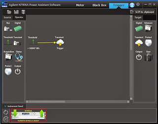
Interestingly this very set up can be programmatically configured within our N6900A and N7900A series Advanced Power System (APS) power supplies. These products have Amp-hour and Watt-hour measurement integrated into their measurement systems. Not only can you measure these parameters, there is a programmable way to act on them in a variety of ways as well, which is the expression signal routing. Logical expressions can be programmed and downloaded into APS, which then acts on them at hardware-level speeds.  Creating and loading the signal routing expression into the APS unit is simplified by using the N7906A Power Assistance software, which let me do it graphically, as shown in Figure 2.


Figure 2: Graphically developing and loading an energy limit setting into an Agilent APS unit

In Figure 2 a threshold comparator was set to generate a trigger output at a level of 0.0047 watt-hours. This trigger was then routed to the output transient system, to cause the output to transition to a new output level when triggered. I had entered in zero volts as the triggered output level. Thus when the watt-hour reading reached its trigger point, the output went to zero, cutting off any more power and energy from being delivered to the DUT.

The SCPI command set for this signal routing expression is also generated from this software utility by clicking on “SCPI to clipboard”. This saves on the effort generating the code manually if you are incorporating the expression into a larger test program. For this expression the code generated is:

:SENSe:THReshold1:FUNCtion WHOur
:SENSe:THReshold1:WHOur 0.0047
:SENSe:THReshold1:OPERation GT
:SYSTem:SIGNal:DEFine EXPRession1,"Thr1"
:TRIGger:TRANsient:SOURce EXPRession1


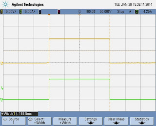
To test things out a 1.18 ohm resistive load was used to draw 84.75 watts for a 10 volt output setting. The output cut back to zero volts at nearly 200 milliseconds, as expected. This is shown in the oscilloscope capture in Figure 3.


Figure 3: APS output for an 84.75 watt load and energy limit set to 0.0047 watt-hours

The load power was then doubled by increasing the output voltage to 14.142 volts. The APS output cut back to zero volts in half the time, delivering the same amount of energy, as expected. This is depicted in the oscilloscope capture in Figure 4.


Figure 4: APS output for a 169.5 watt load and energy limit set to 0.0047 watt-hours

While using a resistor makes it easy to see that a set amount of energy is being delivered to the load. However, being able to act on a real time watt-hour energy measurement makes it very practical to do deliver a fixed amount of energy, regardless of the dynamic nature of the load over time.

Monday, April 8, 2013

Why would a DC power supply have RMS current readback?


During a conversation with a colleague at work one day the topic of having RMS current readback on DC power supplies came up. It is a measurement capability we have on a number of our system DC power supplies. He posed the question: Why the reason for having such a capability? I actually had not been involved with the original investigations identifying what reasons this was added so I instead had to rely on my intuition. That’s not always a good thing but it did help me out this time at least!

He had argued that since you are feeding a fixed DC voltage into the device you are powering, the power consumption is going to be a product of the DC (average) voltage and DC (average) current, regardless of whether the current is purely DC, or if it is dynamic, having a substantial amount of AC content. This is true, as I have illustrated in figure 1, comparing purely DC and pulsed currents being drawn by a load. For purely DC current the DC and RMS values are the same. In comparison, for a pulsed current the RMS value is greater the DC value. Regardless, the RMS current value does not factor into the overall power consumption of the DUT here. The power consumption is still the product of the DC voltage and current.


Figure 1: Comparing power consumption of a DC powered DUT drawing constant and pulsed currents

So why provide an RMS current measurement? Well there can be times when this can prove useful, even when the DUT is powered by a fixed DC voltage. Consider the scenario depicted in Figure 2.


Figure 2: Properly sizing a protection fuse on a DC powered device

Many products incorporate fuses to protect from over-current and subsequent damage, usually brought on due to misuse or component failure. Fuses are rated by their RMS current handling, not the DC current. In the case of the pulsed loading the RMS current is twice the DC current and the resulting power in the fuse is four times that for a constant current.  If the fuse was selected based on the DC current value it would most certainly fail well below the required operating level!

My colleague conceded that this fuse example was a legitimate case where RMS current measurement would indeed be useful. Maybe it was not a frivolous capability after all. No doubt sizing fuses is just one of many reasons why RMS measurement on DC products can be useful!

Monday, January 30, 2012

Watts and volt-amperes ratings – what’s the difference and how do I choose an inverter based on them?

At the end of September, I posted about hurricane Irene and inverters. In that post (click here to read), I talked about the power ratings for inverters and just skimmed the surface about the differences between ratings in watts (W) and volt-amperes (VA). In this post, I want to go further into detail about these differences. Both watts and VA are units of measure for power (in this case, electrical). Watts refer to “real power” while VA refer to “apparent power”.

Inverters take DC power in (like from a car battery) and convert it to AC power out (like from your wall sockets) so you can power your electrical devices that run off of AC (like refrigerators, TVs, hair dryers, light bulbs, etc.) from a DC source during a blackout or when away from home (like when you are camping). Note that this power discussion is centered on AC electrical power and is a relatively short discussion about W, VA, and inverters. Look for a future post with more details about the differences between W and VA.

Watts: real power (W)
Watts do work (like run a motor) or generate heat or light. The watt ratings of inverters and of the electronic devices you want to power from your inverter will help you choose a properly sized inverter. Watt ratings are also useful for you to know if you have to get rid of the heat that is generated by your device that is consuming the watts or if you want to know how much you will pay your utility company to use your device when it is plugged in a wall socket since you pay for kilowatt-hours (power used for a period of time).

The circuitry inside all electronic devices (TVs, laptops, cell phones, light bulbs, etc.) consumes real power in watts and typically dissipates it as heat. To properly power these devices from an inverter, you must know the amount of power (number of watts, abbreviated W) each device will consume. Each device should show a power rating in W on it somewhere (390 W in the picture below) and you can just add the W ratings of each device together to get the total expected power that will be consumed. Most inverters are rated to provide a maximum amount of power also shown in watts (W) – they can provide any number of watts less than or equal to the rating. So, choose an inverter that has a W rating that is larger than the total number of watts expected to be consumed by all of your devices that will be powered by the inverter.


Volt-Amperes: apparent power (VA)
VA ratings are useful to get the amount of current that your device will draw. Knowing the current helps you properly size wires and circuit breakers or fuses that supply electricity to your device. A VA rating can also be used to infer information about a W rating if the W rating is not shown on a device, which can help size an inverter. Volt-amperes (abbreviated VA) are calculated simply by multiplying the AC voltage by the AC current (technically, the rms voltage and rms current). Since VA = Vac x Aac, you can divide the VA rating by your AC voltage (usually a known, fixed number, like 120 Vac in the United States, or 230 Vac in Europe) to get the AC current the device will draw. To combine the apparent power (or current) of multiple devices, there is no straightforward way to get an exact total because the currents for each device are not necessarily in phase with each other, so they don’t add linearly. But if you do simply add the individual VA ratings (or currents) together, the total will be a conservative estimate to use since this VA (or current) total will be greater than or equal to the actual total.


What if your device does not show a W rating?
Some electrical devices will show a VA rating and not a W rating. The number of watts (W) that a device will consume is always less than or equal to the number of volt-amperes (VA) it will consume. So if you need to size an inverter based on a VA rating when no W rating is shown, you will always be safe if you assume the W rating is equal to the VA rating. For example, assume 300 W for the 300 VA device shown in the picture above. This assumption may cause you to choose an oversized inverter, but it is better to have an inverter will too much capacity than one with too little capacity. An inverter with too little capacity will make it necessary for you to unplug some of your devices; otherwise, the inverter will simply turn itself off to protect its own circuitry each time you try to start it up, so it won’t work at all if you try to pull too many watts from it.

Some electrical devices will show a current rating (shown in amps, or A) and not a VA rating or W rating. Usually, this current rating is a maximum expected current. Maximum current usually occurs at the lowest input voltage, so calculate the VA by multiplying the current rating (A) times the lowest voltage shown on the device. Then, assume the device consumes an equal number of W as mentioned in the previous paragraph. For example, the picture below shows an input voltage range of 100 to 240 V and 2 A (all are AC). The VA would be the current, 2 A, times the lowest voltage, 100, which yields 200 VA. You could then assume this device consumes 200 W.