Friday, October 7, 2011

What is line effect and how does it affect my testing?

Line effect is a power supply specification (also known as line regulation or source effect) that describes how well the power supply can maintain its steady-state output setting when the AC input line voltage changes. More formally, it specifies the maximum change in steady-state DC output voltage (or current) resulting from a specified change in the AC input line voltage with all other influence quantities maintained constant. So, when a power supply is regulating its output voltage in CV (constant voltage) mode, this specification tells you how much the voltage can change when the AC input voltage changes. Here is an example:

Let’s say the voltage line effect specification for a 20 V, 5 A power supply is 1 mV and is specified for any line change within ratings. And let’s say that the AC input line voltage range for this power supply for a nominal 120 Vac line is -13% to +6% (104.4 Vac to 127.2 Vac). This means for any AC input line voltage change within the rating of the supply, the output voltage will not change by more than 1 mV. For example, if the power supply is set to 10 V, the actual output may measure 9.999 V at low line (104.4 Vac). (Note that the difference between the setting and the actual output voltage is a different specification called programming accuracy.) If you then increase the AC input line voltage from low line (104.4 Vac) to high line (127.2 Vac), the line effect specification guarantees that the output voltage will not change by more than 1 mV, so it will be somewhere between 9.998 V and 10.000 V. So if the actual output voltage started at 9.999 V at low line and measured 9.9994 V at high line, the line effect for this output when set for 10 V measures 0.4 mV (9.9994 – 9.999), well within the 1 mV specification. You must make the second voltage measurement immediately following the line voltage change to avoid capturing any short-term drift effects.


And what does “with all other influence quantities maintained constant” mean? Things like temperature and output loading can affect the output parameter, so these things must be held constant in order to see only the effect of the line change. The effects on the power supply output of changes in each of these influencing quantities (temperature, output load) are described in different specifications.

Most performance power supplies have line effect specifications of about 1 mV or less. A lower performance model may have a line effect specification of up to 10 mV or more. Power supplies with higher maximum voltage ratings and higher maximum power ratings typically have higher line effect specifications.

If you have an application where maintaining an exact voltage at your DUT is critical and your AC input line can vary throughout the day, you will want to use a power supply with a low line effect specification. If changes in the voltage at your DUT are less critical to you, most power supplies will perform well for your application regardless of line voltage behavior.

Friday, September 30, 2011

Hurricane Irene and inverters

During the weekend of August 27-28, 2011, hurricane Irene wreaked havoc along the east coast of the United States. I live in northern New Jersey where we got more than 10 inches of rain in a short time! Flooding, downed trees, and power outages were rampant! My mother called me during the storm to tell me her basement was flooded. She still lives in the house where I grew up, and I know that basement had not flooded in decades. But she lost power disabling her sump pump, so the heavy rain resulted in several inches of water in the basement saturating the carpet and ruining furniture and other personal items. What a mess! And my brother, who lives in another NJ town, has a restaurant that ended up with 4 feet of water in it!! Fresh fish, anyone?

So when my mother called me for help, I gathered up various tools, buckets, hoses, extension cords, flashlights, my wet/dry vac, and stopped at a friend’s house to borrow an inverter he used when camping (thanks, Andy!). An inverter takes DC in and puts out AC. My hope was to power the inverter from my car battery and plug in my mom’s sump pump to empty out the water in her basement. Luckily, as I was driving to her house with my friend who was coming to help (thanks, Nyla!), my mom called my cell phone to let me know the power was back on, so the sump pump kicked in and pumped out the bulk of the water. Of course, a soggy mess was left behind (7 hours of wet vacuuming made only a small dent in the cleanup, but it was a start). So, it turns out I did not use the inverter at her house (it would not have provided enough power anyway), but when I went to work the next week, I figured I’d play around with it in our lab area. Here are some of the things I found…

This inverter is a Coleman Powermate (model PMP400) 400 W inverter. It takes 12 V DC in and has a 40 A fuse on the input side, and two outlets with an on/off switch on the output side.


The output is a modified sine wave (looks more like a modified square wave to me, but OK, I’ll call it by its rightful name), at nominally 120 Vrms and 60 Hz, which are the standard AC mains voltage and frequency in the US. The waveform below was captured with a scope (an Agilent MSO7054A) and shows the actual output of the inverter with 12V DC in (from an Agilent N6754A installed in an N6705A) and a light load (~32 W) on the output.


Below is what the standard AC line looks like in the US, so you can see that the inverter's output (shown above) is only an approximation of the waveshape, although the inverter does maintain the correct rms voltage and frequency:


As a load on the inverter, I powered up another one of our DC power supplies (an Agilent 66332A) by plugging it into the inverter output. I could then program the output of the 66332A power supply to a voltage (20 V), connect it to one of our DC electronic loads (an Agilent 6063B) and vary the load current (up to nearly 5 A), thereby changing the loading on the 66332A, which in turn, changed the load on the inverter.


The inverter output frequency remained very close to 60 Hz for all loading conditions, and the output voltage dropped slightly (just a few volts) as I increased the loading on the inverter. The maximum power I drew from the inverter was limited by my input power source, the N6754A, which is a 300 W, 60 V, 20 A power supply. Since I was using it at 12 V, I set the current limit on it to the maximum of 20 A providing a maximum of about 240 W to the inverter input. So I was able to exercise the inverter up to only a little over one half of its 400 W capability.

The 66332A power supply I used as my load for the inverter has a standard AC input and seemed to operate just fine when powered by the modified sine wave coming from the inverter output. Regarding other loads you might plug into the output of an inverter, I think most AC motors would operate when supplied by a modified sine wave, however other devices such as audio equipment, fluorescent lighting, and some laser printers might not work properly or at all. Inverters are available with pure sine wave outputs to more closely mimic the power supplied by your utility company, however, these tend to be much more costly – sometimes several times the cost of an equally powered modified sine wave inverter.

I looked up a few numbers about waveforms and found that a pure square wave has a THD of about 45% while a modified sine wave has a THD of about 24%. Here is an interesting article on this topic:
http://powerelectronics.com/mag/608PET21.pdf

So if you ever lose AC mains power and need to run one or more AC powered devices, you could temporarily use an inverter powered from your car battery. Just be sure to get an inverter with enough power to handle the load you will put on it, and make sure the type of inverter you choose (modified or pure sine wave output) is appropriate for the load you want to power. Although it turned out I did not need it for my mom’s sump pump, the 400 W inverter I borrowed would not have been powerful enough for the pump. The current rating on the pump was about 6 A, so at 120 V, that is 720 VA (120 V x 6 A) which is more than the 400 W inverter could provide. But how do you compare VA (volt-amperes) to W (watts), you ask? The power that a device consumes expressed in W will always be less than or equal to the power in VA, but I’ll leave that discussion for another post! For now, if you think you’ll need an inverter, get one with a W rating higher than the total VA you require. This approach may be a bit overkill, but you will definitely have enough power.

Wednesday, September 21, 2011

What is load effect and how does it affect my testing?

Load effect is a power supply specification (also known as load regulation) that describes how well the power supply can maintain its steady-state output setting when the load changes. More formally, it specifies the maximum change in steady-state DC output voltage (or current) resulting from a specified change in the load current (or voltage), with all other influence quantities maintained constant. So, when a power supply is regulating its output voltage in CV (constant voltage) mode, this specification tells you how much the voltage can change when the current changes. Here is an example:

Let’s say the voltage load effect specification for a 20 V, 5 A power supply is 2 mV and is specified for any load change. This means for any current change within the rating of the supply (in this case, up to 5 A), the output voltage will not change by more than 2 mV. For example, if the power supply is set to 10 V, the actual output may measure 9.999 V with no load (0 A). (Note that the difference between the setting and the actual output voltage is a different specification called programming accuracy.) If you then increase the current from 0 A to a full load condition of 5 A, the load effect specification guarantees that the output voltage will not change by more than 2 mV, so it will be somewhere between 9.997 V and 10.001 V. So if the actual output voltage started at 9.999 V with a 0 A load and measured 9.9982 V with a 5 A load, the load effect for this output when set for 10 V measures 0.8 mV (9.999 – 9.9982), well within the 2 mV specification. You must make the second voltage measurement immediately following the load current change to avoid capturing any short-term drift effects.


In the above example, the specified change in load current was “any load change”. Of course, it is implied that the load change is within the output ratings of the supply. You cannot change the output current from 0 A to 100 A on a 5 A power supply. Some load effect specifications state that the load change is a 50% change (e.g., 2.5 A to 5 A) while others may say 10% to 90% of full load (e.g., 0.5 A to 4.5 A).

And what does “with all other influence quantities maintained constant” mean? Things like temperature and the AC line input voltage can affect the output parameter, so these things must be held constant in order to see only the effect of the load change. The effects on the power supply output of changes in each of these influencing quantities (temperature, AC line input voltage) are described in different specifications.

Most performance power supplies have load effect specifications in the range of just a few hundred uV up to a few mV. A lower performance model may have a load effect specification of between 10 mV and 100 mV. Power supplies with higher maximum voltage ratings and higher maximum power ratings typically have higher load effect specifications.

If you have an application where maintaining an exact voltage at your DUT is critical and your DUT draws different amounts of current at different times, you will want to use a power supply with a low load effect specification. If changes in the voltage at your DUT with changes in DUT current are less critical to you, most power supplies will perform well for your application.

Wednesday, August 31, 2011

Ideal Versus Real: Understanding Some Fundamentals When Selecting Power Supplies

Introduction
In college, we learned about electronics using ideal components: pure resistors without series inductance, pure capacitors without ESR, op amps with infinite gain and zero offset voltage. For power supplies, the situation was no different: a constant voltage source with zero output impedance, unlimited current compliance, and infinite bandwidth. With components like these, how difficult could it be to design electronic circuits and systems?

Then, we got jobs as engineers in the real world and discovered things like temperature coefficients in resistors, dielectric absorption in capacitors, and phase shifts in the gain of amplifiers. Power supplies did not escape the omnipotent forces determined to destroy our idealistic view of electronics. Non-zero output impedance, output current limitations, and finite bandwidth have all conspired to make our lives a little more complicated when applying power supplies. The effects of these non-ideal power supply attributes and others are discussed in this post.

The Ideal Voltage Source
An ideal voltage source would maintain its output voltage constant irrespective of the loading conditions. For example, if the source were a 5 V DC source, the output would measure exactly 5.0 V with no current flowing, or with 1 A flowing, or 10 A, or 500 A, and so on. Additionally, when the load current changed from one value to another, such as from 5 A to 10 A, the output voltage would be maintained at exactly 5.0 V, unperturbed throughout the change. See Figure 1a.

The Real Voltage Source
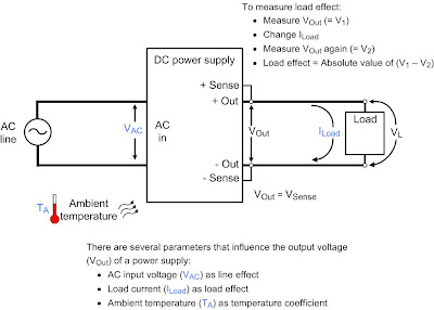
Unfortunately, power supplies like the ideal one described above do not exist in real life. Real power supplies try to maintain a constant voltage on their outputs by employing a feedback loop that monitors the output voltage, compares that voltage to a reference, and continuously makes adjustments based on the difference. They also have to be designed to fit in a limited space, with limited input power, and limited ability to dissipate the inevitable heat generated internally. Consequently, real power supplies have limited current compliance, finite output impedance, and finite bandwidth. The effects of these attributes become apparent when drawing current from the power supply, whether that is a static current or dynamic current. For example, a 5.0 V output at no load with 10 milliohms of output impedance will drop to 4.9 V with a 10 A static load. The output voltage will continue to decrease as the current increases. See Figure 1b.

With dynamic loads, the non-ideal nature of the real power supply output becomes more evident. Consider the output voltage behavior shown in Figure 1b immediately following the load current changes. The voltage overshoots and undershoots of the real source are a result of its non-zero output impedance which is a function of frequency (Zo(f)) and is determined by the internal feedback loop used to maintain the output voltage.


Power Supply Output – Deviant Behavior?
When selecting a power supply to meet your needs, first make sure you know what output voltage deviations you can tolerate. Evaluate your needs with respect to both static and dynamic conditions. For example, some devices, such as cell phones, have a low voltage detection circuit built-in. Make sure you are aware of the voltage level at which this circuit takes effect and how long the voltage must be below that level for the circuit to trip. The power supply used for testing should be selected to maintain its output voltage to meet your needs under changing load current conditions, especially to avoid nuisance tripping of a low voltage detection circuit. The load regulation (or load effect) specification tells you how well the power supply will maintain its output voltage when subjected to static load changes. The transient response specification will tell you how long it will take for the output voltage to recover to within a voltage band around the output voltage following a current change. Power supplies with different performance levels have correspondingly different specifications as shown in the table.


Other Non-ideal Attributes to Consider
In addition to the output voltage response to static and dynamic load changes, real power supplies also exhibit many other non-ideal behaviors. Line regulation, output noise, and cross regulation for multiple output power supplies are some examples.
  • Line regulation is a measure of how the output voltage responds statically to input line voltage changes. It is primarily caused by finite loop gain, with some secondary effects from internal bias supply line regulation effects.
  • Output noise is usually specified in either peak-to-peak volts, or rms volts, or both, and within a specified bandwidth such as 20 Hz to 20 MHz. Output noise has many sources, including residual effects from rectification circuits, internal digital circuits, and even the op amps themselves that are used for output voltage regulation.
  • On a multiple output power supply, cross regulation is a measure how one output voltage responds to load current changes on the other output(s).
Clearly, for all of these attributes, the lower the specified behavior, the more “ideal” the power supply. While it may be tempting to look for a power supply with the lowest specifications in all of these areas, it is always prudent to evaluate your true needs, and make your selection based on those needs. Since tradeoffs must often be made, knowing your requirements will always make the selection process easier by broadening the choices when compared to just looking for the best specifications in all areas.

Other, more subtle behavior of non-ideal power supply outputs can also be important, depending on your application:
  • Overshoots at AC (or DC) input turn-on and turn-off should be considered.
  • Output voltage behavior when the power supply enters or leaves a current limit condition (mode crossover overshoots) can sometimes cause problems.
These behaviors are often unspecified by the power supply manufacturer. However, relying on reputable power supply vendors helps avoid problems since these vendors frequently take steps during the design process to minimize these effects.

Wrap-up
Obviously, real power supplies don’t behave like ideal power supplies. Sometimes this non-ideal behavior makes a difference in your application, and sometimes it does not. When selecting a power supply, it is important for you to know your true requirements in order to make the selection process go as smoothly as possible and to avoid overspending. A power supply’s specifications outline its non-ideal behavior, so look for specifications that meet your needs. Also realize that there are unspecified performance issues that could be important in your application as well. If you don’t see the specification for which you have interest, ask your power supply vendor about parameters you feel are important in your application.

Thursday, August 25, 2011

Use Remote Sense to Regulate Voltage at Your Load

Have you ever set your power supply output voltage to a particular value and found the voltage at your load was lower than you expected? If this was acceptable for your test, then you probably just left it alone. But if you wanted the voltage at your load to be equal to the voltage you set, then you should have used remote sensing.

Remote sensing is a feature on many power supplies that allows the power supply to regulate the voltage right at your load (“remotely”). This is accomplished by using a set of remote sense leads that are in addition to your load leads. The power supply uses the voltage on the remote sense lead terminals to sense the voltage right at the load terminals and regulate the voltage right at the load by adjusting the output terminal voltage.

Consider the example in Figure 1 showing a power supply set for 5 V, the desired voltage at the load. If the load is located six feet away from the output terminals, and you are using 14 AWG wire (about 2.5 mΩ/ft), each load lead will have about 0.015 Ω of resistance. If 10 A is flowing through the load leads, each load lead will drop about 0.15 V (10 A x 0.015 Ω) for a total drop of 0.3 V. When the power supply regulates its output voltage right at the output terminals, the result at the load is 4.7 V instead of the desired 5 V.


Figure 2 shows the same setup using remote sensing. The remote sense terminals are connected to the load at the points where you want the 5 V setting to be regulated. In this case, the power supply regulates 5 V at the load by adjusting its output voltage to 5.3 V to make up for the drops in the load leads. It does this by using the voltage across the sense leads as part of the feedback loop inside the power supply to adjust the voltage on the output terminals. The purpose of the power supply is to keep the sense lead voltage constant at the setting; the power supply changes the output terminal voltage based on the sense terminal voltage. The input impedance of the sense terminals is high enough to prevent any significant current flow into the sense terminals – this makes any voltage drop on the sense leads themselves negligible.

Tuesday, July 26, 2011

"Where's the CC button?"

I have worked at Agilent (was HP, of course) for more than 30 years now (since 1980) and I have spent the majority of that time involved with power products. One thing has been consistent over that period of time: we are asked about how to put a power supply in constant current (CC) mode. The question takes on many forms, one of which is "Where's the CC button?". Given that this is my first blog post, and given that this is an important fundmental concept about power supplies, I figured it was a good place to start this power blog. Well, the simple answer is: there is no CC button, but continue reading to find out how to "put" a power supply in CC mode....

There are two primary output operating modes for most power supplies: constant voltage (CV) mode and constant current (CC) mode. While you don't set the mode, you do set the output voltage setting and the output current setting. Then, the output operating mode is determined by what you connect to the output (the load).

The output operating mode is detemined by three things:

  1. Output voltage setting (Vset)

  2. Output current setting (Iset)

  3. Load value (Rload)


If the load current is low enough such that the current that is drawn is LESS than the current setting, the power supply will operate in CV mode regulating the voltage at a constant value with the current determined by the load.

If the load current is high enough such that the load is trying to draw MORE current than the current setting, the power supply will limit the current at the current setting value and operate in CC mode regulating the current with the voltage determined by the load.

Consider a simple resistive load, Rload:
If Rload > Vset / Iset, the power supply will be operating in CV mode.
If Rload < Vset / Iset, the power supply will be operating in CC mode.


The two extreme examples of the above are with Rload open (near infinite ohms) and Rload shorted (near zero ohms). When a power supply output is open (Rload = infinite, a vertical line from the origin on the graph), it should be obvious that the output will be in CV mode with no current flowing. When a power supply output is shorted (Rload = zero, a horizontal line from the origin on the graph), it should be obvious that the output will be in CC mode with near zero voltage.

Note that Agilent power supplies typically show the dynamic operating mode on the front panel. If the power supply is unable to regulate either the voltage or the current, the indicator will show UNR (unregulated) since neither the voltage nor the current is being regulated. This condition is rare, but can happen sometimes if Rload = Vset/Iset, or if there is a problem with the internal circuitry.