Thursday, March 29, 2012

Protect your DUT with power supply features including a watchdog timer

The two biggest threats of damage to your device under test (DUT) from a power supply perspective are excessive voltage and excessive current. There are various protection features built into quality power supplies that will protect your DUT from exposure to these destructive forces. There are also some other not-so-common features that can prove to be invaluable in certain applications.

Soft limits
The first line of defense against too much voltage or current can be using soft limits (when available). These are maximum values for voltage and current you can set that later prevent someone from setting output voltage or current values that exceed your soft limit settings. If someone attempts to set a higher value (either from the front panel or over the programming interface), the power supply will ignore the request and generate an error. While this feature is useful to prevent accidentally setting voltages or currents that are too high, it cannot protect the DUT if the voltage or current actually exceeds a value due to another reason. Over-voltage protection and over-current protection must be used for these cases.

Over-voltage protection
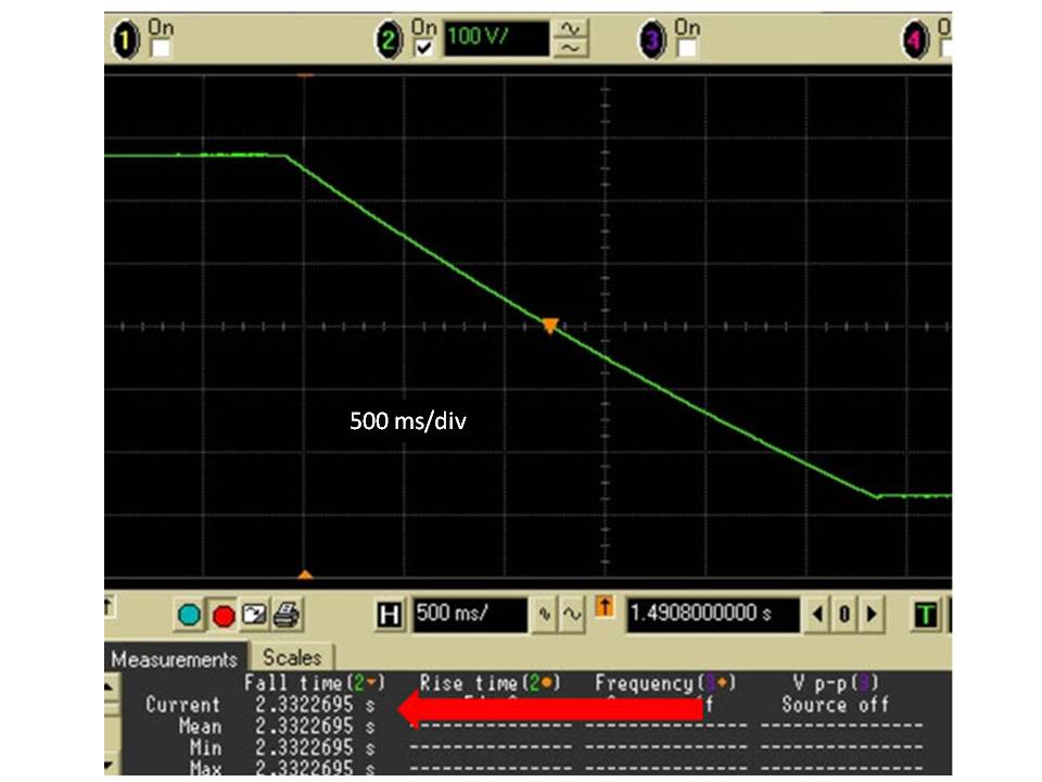
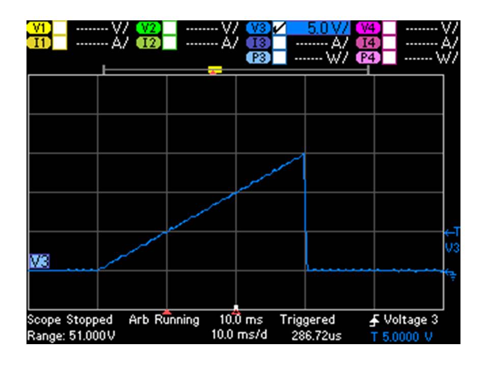
Over-voltage protection (OVP) is a feature that uses an OVP setting (separate from the output voltage setting). If the actual output voltage reaches or exceeds the OVP setting, the power supply shuts down its output, protecting the DUT from excessive voltage. The figure below shows a power supply output voltage heading toward 20 V with an OVP setting of 15 V. The output shuts down when the voltage reaches 15 V.

Some power supplies have an SCR (silicon-controlled rectifier) across their output that gets turned on when the OVP trips essentially shorting the output as quickly as possible. Again, the idea here is to protect the DUT from excessive voltage by limiting the voltage magnitude and exposure time as much as possible. The SCR circuit is sometimes called a “crowbar” circuit since it acts like taking a large piece of metal, such as a crowbar, and placing it across the power supply output terminals.

Over-current protection
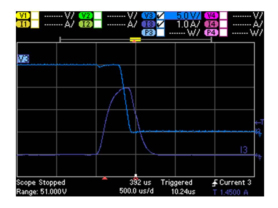
Over-current protection (OCP) is a feature that uses the constant current (CC) setting. If the actual output current reaches or exceeds the constant current setting causing the power supply to go into CC mode, the power supply shuts down its output, protecting the DUT from excessive current. The figure below shows a power supply output current heading toward 3 A with a CC setting of 1 A and OCP turned on. The power supply takes just a few hundred microseconds to register the over-current condition and then shut down the output. The CC and OCP circuits are not perfect, so you can see the current exceed the CC setting of 1 A, but it does so for only a brief time.

The OCP feature can be turned on or off and works in conjunction with the CC setting. The CC setting prevents the output current from exceeding the setting, but it does not shut down the output if the CC value is reached. If OCP is turned off and CC occurs, the power supply will continue producing current at the CC value basically forever. This could damage some DUTs as the undesired current flows continuously through the DUT. If OCP is turned on and CC occurs, the power supply will shut down its output, eliminating the current flowing to the DUT.

Note that there are times when briefly entering CC mode is expected and an OCP shutdown would be a problem. For example, if the load on the power supply has a large input capacitor, and the output voltage is set to go from zero to the programmed value, the cap will draw a large inrush current that could temporarily cause the power supply to go into CC mode while charging the cap. This short time in CC mode may be expected and considered acceptable, so there is another feature associated with the OCP setting that is a delay time. Upon a programmed voltage change (such as from zero to the programmed value as mentioned above), the OCP circuit will temporarily ignore the CC status just for the delay time, therefore avoiding nuisance OCP tripping.

Remote inhibit
Remote inhibit (or remote shutdown) is a feature that allows an external signal, such as a switch opening or closing, to shutdown the output of the power supply. This can be used for protection in a variety of ways. For example, you might wire this input to an emergency shutdown switch in your test system that an operator would use if a dangerous condition was observed such as smoke coming from your DUT. Or, the remote inhibit could be used to protect the test system operator by being connected to a micro switch on a safety cover for the DUT. If dangerous voltages are present on the DUT when operating, the micro switch could disable DUT power when the cover is open.

Watchdog timer
The watchdog timer is a unique feature on some Agilent power supplies, such as the N6700 series. This feature looks for any interface bus activity (LAN, GPIB, or USB) and if no bus activity is detected by the power supply for a time that you set, the power supply output shuts down. This feature was inspired by one of our customers testing new chip designs. The engineer was running long-term reliability testing including heating and cooling of the chips. These tests would run for weeks or even months. A computer program was used to control the N6700 power supplies that were responsible for heating and cooling the chips. If the program hung up, it was possible to burn up the chips. So the engineer expressed an interest in having the power supply shut down its own outputs if no commands were received by the power supply for a length of time indicating that the program has stopped working properly. The watchdog timer allows you to set delay times from 1 to 3600 seconds.

Other protection features that protect the power supply itself
There are some protection features that indirectly protect your DUT by protecting the power supply itself, such as over-temperature (OT) protection. If the power supply detects an internal temperature that exceeds a predetermined limit, it will shut down its output. The temperature may rise due to an unusually high ambient temperature, or perhaps due to a blocked or incapacitated cooling fan. Shutting down the output in response to high temperature will prevent other power supply components from failing that could lead to a more catastrophic condition.

One other way in which a power supply protects itself is with an internal reverse protection diode across its output terminals. As part of the internal design, there is often a polarized electrolytic capacitor across the output terminals of a power supply. If a reverse voltage from an external power source was applied across the output terminals, the cap (or other internal circuitry) could easily be damaged. The design includes a diode across the output terminals with its cathode connected to the positive terminal and its anode connected to the negative terminal. The diode will conduct if a reverse voltage from an external source is applied across the output terminals, thereby preventing the reverse voltage from rising above a diode drop and damaging other internal components.

Wednesday, March 28, 2012

What Is Going On When My Power Supply Displays “UNR”?

Most everyone is familiar with the very traditional Constant Voltage (CV) and Constant Current (CC) operating modes incorporated in most any lab bench or system power supply. All but the most very basic power supplies provide display indicators or annunciators to indicate whether it is in CV or CC mode. However, moderately more sophisticated power supplies provide additional indicators or annunciators to provide increased insight and more information about their operating status. One annunciator you may encounter is seeing “UNR” flash on, either momentarily or continuously. It’s fairly obvious that this means that the power supply is unregulated; it is failing to maintain a Constant Voltage or Constant Current. But what is really going on when the power supply displays UNR and what things might cause this?
To gain better insight about CV, CC and UNR operating modes it is helpful to visualize what is going on with an IV graph of the power supply output in combination with the load line of the external device being powered. I wrote a two part post about voltage and current levels and limits which you may find useful to review. If you like you can access it from these links levels and limits part 1 and levels and limits part 2. This posting builds nicely on these earlier postings. A conventional single quadrant power supply IV graph with resistive load line is depicted in Figure 1. As the load resistance varies from infinity to zero the power supply’s output goes through the full range of CV mode through CC mode operation. With a passive load like a resistor you are unlikely to encounter UNREG mode, unless perhaps something goes wrong in the power supply itself.
Figure 1: Single quadrant power supply IV characteristic with a resistive load

However, with active load devices you have a pretty high chance of encountering UNR mode operation, depending where the actual voltage and current values end up at in comparison to the power supply’s voltage and current settings. One common application where UNR can be easily encountered is charging a battery (our external active load device) with a power supply. Two different scenarios are depicted in Figure 2. For scenario 1, when the battery voltage is less than the power supply’s output, the point where the power supply’s IV characteristic curve and the battery’s load line (a CV characteristic) intersect, the power supply is in CC mode, happily supplying a regulated charge current into the battery. However, for scenario 2 the battery’s voltage is greater than the power supply’s CV setting (for example, you have your automobile battery charger set to 6 volts when you connect it to a 12 volt battery). Providing the power supply is not able to sink current the battery forces the power supply’s output voltage up along the graph’s voltage axis to the battery’s voltage level. Operating along this whole range of voltage greater than the power supply’s output voltage setting puts the power supply into its UNR mode of operation.
Figure 2: Single quadrant power supply IV characteristic with a battery load

A danger here is more sophisticated power supplies usually incorporate Over Voltage Protection (OVP). One kind of OVP is a crowbar which is an SCR designed to short the output to quickly bring down the output voltage to protect the (possibly expensive) device being powered. When connected to a battery if an OVP crowbar is tripped, damage to the power supply or battery could occur due to batteries being able to deliver a fairly unlimited level of current. It is worth knowing what kind of OVP there is in a power supply before attempting to charge a battery with it. Better yet is to use a power supply or charger specifically designed to properly monitor and charge a given type of battery. The designers take these things into consideration so you don’t have to!
I have digressed here a little on yet another mode, OVP, but it’s all worth knowing when working with power supplies! Can you think of other scenarios that might drive a power supply into UNR? (Hint: How about the other end of the power supply IV characteristic, where it meets the horizontal current axis?)

Tuesday, March 27, 2012

If you need fast rise and fall times for your DUT power, use a power supply with a downprogrammer

If you have to provide DC power to a device under test (DUT) and you want the voltage fall time to be just as fast as the rise time, use a power supply with a downprogrammer. A downprogrammer is a circuit built into the output of a power supply that actively pulls the output voltage down when the power supply is moving from a higher setting to a lower setting. Power supplies are good at forcing their output voltage up since that is what their internal circuitry is designed to do. This design results in fast rise times. However, when the supply’s output is changed to move down in voltage, the power supply’s output capacitor (and any additional external DUT capacitance) will need to be discharged. Without a downprogrammer, if there is a light load or no load on the output of the power supply, there is nowhere for the current from the output cap to flow to discharge it. This scenario causes the voltage to take a long time to come down resulting in slow fall times. And this behavior leads to longer test times since you will have to wait for the output voltage to settle to the lower value before you can proceed with your test.

The figures below show an example of the output voltage rise and fall times of a power supply without a downprogrammer under light load conditions. You can see the short rise time (tens of milliseconds) and longer fall time (several seconds).


One of my colleagues, Bob Zollo, wrote an article on this topic that appeared in Electronic Design on February 7, 2012. Here is a link to the article:

http://electronicdesign.com/article/test-and-measurement/If-Your-Power-Supply-Needs-Fast-Rise-And-Fall-Times-Try-A-Down-Programmer-64725

A power supply without an active downprogrammer can have fall times that are tens to hundreds of times longer than a power supply with a downprogrammer. If your test requires you to have fast fall times for your DUT power, or your test requires you to frequently change the voltage on your DUT (both up and down) and throughput is an issue for you, make sure the power supply you choose has a downprogrammer – you won’t have to wait as long for the voltage to move from a higher value to a lower value.

Wednesday, March 21, 2012

Using Current Drain Measurements to Optimize Battery Run-time of Mobile Devices

One power-related application area I do a great deal of work on is current drain measurements and analysis for optimizing the battery run-time of mobile devices. In the past the most of the focus has been primarily mobile phones. Currently 3G, 4G and many other wireless technologies like ZigBee continue to make major inroads, spurring a plethora of new smart phones, wireless appliances, and all kinds of ubiquitous wireless sensors and devices. Regardless of whether the device is overly power-hungry due to running data-intensive applications or power-constrained due to its ubiquitous nature, there is a need to optimize its thirst for power in order to get the most run-time from its battery. The right kind of measurements and analysis on the device’s current drain can yield a lot of insight on the device’s operation and efficiency of its activities that are useful for the designer in optimizing its battery run-time. I recently completed an article that appeared in Test & Measurement World, on-line back in November and then in print in their Dec 2011- Jan 2012 issue. Here is a link to the article:
http://www.tmworld.com/article/520045-Measurements_optimize_battery_run_time.php

A key factor in getting current drain measurements to yield the deeper insights that really help optimize battery run-time is the dynamic range of measurement, both in amplitude and in time, and then having the ability to analyze the details of these measurements. The need for a great dynamic range of measurement stems from the power-savings nature of today’s wireless battery powered devices. For power-savings it is much more efficient for the device to operate in short bursts of activities, getting as much done as possible in the shortest period of time, and then go into a low power idle or sleep state for an extended period of time between these bursts of activities. Of course the challenge for the designer to get his device to quickly wake up, stabilize, do its thing, and then just as quickly go back to sleep again is no small feat! As one example the current drain of a wireless temperature transmitter for its power-savings type of operation is shown in Figure 1.


Figure 1: Wireless temperature transmitter power-savings current drain

The resulting current drain is pulsed. The amplitude scale has been increased to 20 µA/div to show details of the signal’s base. This particular device’s current drain has the following characteristics:
• Period of ~4 seconds
• Duty cycle of 0.17%
• Currents of 21.8 mA peak and 53.7 µA average for a crest factor of ~400
• Sleep current of 7 µA
This extremely wide dynamic range of amplitude is challenging to measure as it spans about 3 ½ decades. Both DC offset error and noise floors of the measurement equipment must be extremely low as to not limit needed accuracy and obscure details.

Likewise being able to examine details of the current drain during the bursts of activities provides insights about the duration and current drain level of specific operations within the burst. From this you can make determinations about efficiencies of the operations and if there is opportunity to further optimize them. As an example, in standby operation a mobile phone receives in short bursts about every 0.25 to 1 seconds to check for incoming pages and drops back into a sleep state in between the receive (RX) bursts. An expanded view of one of the RX current drain bursts is shown in figure 2.


Figure 2: GPRS mobile phone RX burst details

There are a number of activities taking place during the RX burst. Having sufficient measurement bandwidth and sampling time resolution down to 10’s of µsec provides the deeper insight needed for optimizing these activities. The basic time period for the mobile phone standby operation is on the order of a second but it is usually important to look at the current drain signal over an extended period of time due to variance of activities that can occur during each of the RX bursts. Having either a very deep memory, or even better, high speed data logging, provides the dynamic range in time to get 10’s of µsec of resolution over an extended period of time, so that you can determine overall average current drain while also being able to “count the coulombs” it takes for individual, minute operations, and optimize their efficiencies.

Anticipate seeing more here in future posts about mobile wireless battery-powered devices, as it relates to the “DC” end of the spectrum. In the meantime, while you are using your smart phone or tablet and battery life isn’t quite meeting your expectation (or maybe it is!), you should also marvel at how capable and compact your device is and how far it has come along in contrast to what was the state-of-the-art 5 and 10 years ago!

Wednesday, February 29, 2012

On DC Source Voltage and Current Levels and (Compliance) Limits Part 2: When levels and limits are not the same

In part 1 my colleague made a good argument for current and voltage level and limit settings actually being one and the same thing and it was really just a case of semantics whether your power supply was operating in constant voltage or in constant current mode. I disagreed and I was not ready to admit defeat on this yet. Now is my chance to explain why I believe they’re not one and the same thing.

I have been doing quite a bit of work with source measure units (SMUs) that support multi quadrant output operation. They in fact feature (constant) voltage sourcing and current sourcing modes of operation. This tailors the operation of the SMU for operating as a voltage source with a set current compliance range or conversely as a current source with a set voltage compliance range. Right at the start one difference is the set up conditions. The output voltage or current level is set to zero while the corresponding current or voltage limit is set to some value, often maximum, so that the DC source accordingly starts out in either constant voltage or constant current for normal operating conditions.

Some products feature a programmable or fixed power limits. In one product I know of, the programmable power limit acts accordingly to override and cut back the either the voltage limit when set for current sourcing, or the current limit when set for voltage sourcing. It does not do this in true real-time however. It cuts back the limit based on the level setting, as a convenient means as to help prevent the user from accidently over-powering the DUT. Alternately many auto-ranging output DC power sources exist that provide an extended range of output and voltage for a given output power capacity. They incorporate a fixed power limit to protect the power supply itself from being inadvertently overloaded, as shown in Figure 1. Usually the idea is for the user to stay below the limit, not operate in power limit. The point here on these examples is that the power parameter is an example of being a limit but not really a level.

Figure 1: Auto-ranging DC power supply power limit

More to the point is some SMUs may incorporate two limits to provide a bounded compliance range with specified positive and negative limits. Not all DUTs are passive, non-reactive devices. As one illustrative example a DUT may be the output of 2-quadrant DC voltage source which you want to force up or down, within limits, or a battery you want to charge and discharge at a fixed rate, with your test system DC source. This set up is illustrated in Figure 2.

Figure 2: Test system DC source driving the output of a DUT source

Figure 3 shows the constant voltage or voltage priority output characteristic for one particular SMU having two programmable current limits. Clearly both limits cannot also be the current level setting as you can only have one level setting. For the case of the external voltage source load line #1 (not all load lines are resistances!), when SMU voltage is less than the DUT source voltage (VEXT1 load line), the current is –ILIM. Conversely when SMU voltage is greater than the DUT source voltage (VEXT2 load line), the current is then +ILIM. In the case of the battery as a DUT this can be used to charge and discharge the battery to specified voltage levels. This desired behavior is achieved using voltage priority operation. Current priority operation would yield very different results. Understanding the nuances of voltage priority, current priority, levels, and limits is useful for getting more utility from your DC sources for more unusual and challenging power test challenges.

Figure 3: Example of a current priority output characteristic driving a DUT voltage source

In closing I’ll concur with my colleague, in many test situations using most DC sources the voltage and current levels and limits may not have a meaningful difference. However, in many more complex cases, especially when dealing with active DUTs and using more capable DC sources and SMUs, there is a clear need for voltage and current level and limit controls that are clearly differentiated and not one and the same! What do you believe?

Wednesday, February 22, 2012

On DC Source Voltage and Current Levels and (Compliance) Limits Part 1: When levels and limits are one and the same

I was having a discussion with a colleague about constant current operation versus constant voltage operation and the distinction between level settings and limit settings the other day. “The level and limit settings are really the same thing!” he claimed. I disagreed. We each then made ensuing arguments in defense of our positions.

He based his argument on the case of a DC power supply that has both constant voltage and constant current operation. I’ll agree that is a reasonable starting point. As a side note there is a general consensus here that if it isn’t a true, well regulated constant voltage or constant current, whether settable or fixed, then it is simply a limit, not a level setting, end of story. He continued “if the load on the power supply is such that it is operating in constant voltage, then the voltage setting is the level setting and the current setting is the limit setting. If the load increases such that the power supply changes over from constant voltage operation into constant current operation then the voltage setting is becomes the limit setting and the current setting becomes the level setting!” (See figure 1.) He certainly has a good point! For your more basic DC power supply that only operates in quadrant 1 capable of sourcing power only, the current and voltage settings usually interchangeably serve as both the level and compliance limit setting, depending on whether the DC power supply is operating in constant voltage or constant current. The level and compliance limit regulating circuits are one and the same. Likewise with the programming, there are only commands to set the voltage and current levels. There are not separate commands for the limits. I might be starting to lose grounds on this discussion!
Figure 1: Unipolar single quadrant DC source operation

However, all is not lost yet. The DC power supply world is often more complicated than just this unipolar single quadrant operation just presented. Watch for my second part on when the levels and limits are not necessarily one and the same.

Friday, February 17, 2012

The economics of recharging your toy helicopter

While on a business trip visiting customers in Taiwan back in December, I got a toy helicopter as a thank-you gift from one of my coworkers (thanks, Sharon!). This toy helicopter is fun to fly and is surprisingly stable in the air.


Flight time is about 7 minutes, and the battery recharge time is about 40 minutes. It can be recharged from a powered USB port by using a wire that came with the toy that has a USB connector on one end and the helicopter charging connector on the other end. Or, it can be recharged from the six AA alkaline batteries inside the handheld controller via a wire that exits from the controller. Thinking I did not want to prematurely drain the controller batteries, I typically used the USB charging method by using my iPad’s 10 W USB power adapter plugged into a wall outlet. So I got to thinking about which charging method was more economical: charging from a wall outlet or from the batteries. Luckily, I have test equipment at my disposal that can help me answer that question!


Recharging using AC power via USB power adapter
Using one of our Agilent 6812B AC sources, I captured the AC power used during a recharge cycle. I used the AC source GUI to take readings of power every second for the charge period and plotted it in a spreadsheet (graph shown below). I found that the power consumed started at about 2.2 W and ended at about 1.2 W roughly 41 minutes later. The energy used during this time was 1.1 W-hours. Where I live in New Jersey, the utility company charges about 15 cents per kilowatt-hour, so 1.1 W-hours of energy used to charge the helicopter costs fractions of a penny (0.0165 cents = US$ 0.000165). This is basically nothing!


Recharging using controller battery power
To analyze the current drawn from the controller batteries, I used one of our Agilent N6705B DC power analyzers with an N6781A SMU module installed. I ran the battery current path through the SMU set for Current Measure mode and used our 14585A Control and Analysis software. I captured the current drawn from the six AA batteries in the controller during the helicopter recharge cycle. These batteries are in series, so the same current flows through each of the six batteries and also through the SMU for my test.


For the recharge period (about 43 minutes using this method), the software shows the batteries provided 173 mA-hours of charge to the helicopter. A typical AA alkaline battery is rated for 2500 mA-hours, so that means I would get about 14 (= 2500/173) charge cycles from these six batteries. If you shop around for high-quality AA batteries, you might find them for as low as 25 cents per battery. Since the controller takes six of these, the battery cost for the controller is $1.50. If I can recharge the helicopter 14 times with $1.50 worth of batteries, each recharge cycle costs about 10.7 cents (= US$ 0.107). This is 650 times more expensive than using the AC power method, so I will continue using the wall outlet to recharge my toy helicopter! How about you?
Note that with the AC power recharge method, you pay for the kilowatt-hours you consume from your utility company. With the controller battery power method, you pay for the mA-hours you consume from your batteries. Consider this: if you choose the AC power method, you will save US$ 0.106835 per recharge cycle. That means after just 2.81 million recharge cycles, you will have saved enough money to buy yourself a real helicopter worth US$ 300,000, so you better get started now!