Friday, September 27, 2013

New Agilent Autoranging Power Supplies provide Higher Power

I have stated before that I avoid posting product-only-focused material in this blog since our intention here is to educate about all-things-power rather than to (directly) promote our products. But when we (Agilent….for now…) come out with new power products, I think it is appropriate for me to announce them here. The last time I did this was back on January 23, 2012 in this post:


Coincidentally, those products were autoranging power supplies just like some of the power products we just introduced! Earlier this month, Agilent announced two new families of high-power system power supplies with this press release:

http://www.agilent.com/about/newsroom/presrel/2013/04sep-em13103.html

The two new families are the:
·         N6900/N7900 Series 1- and 2-kW Advanced Power System (APS) DC Power Supplies
·         N8900 Series 5-, 10-, and 15-kW Autoranging DC Power Supplies

Today I will focus on the higher power series, the N8900. Next week, I’ll post about the N6900/N7900 series.

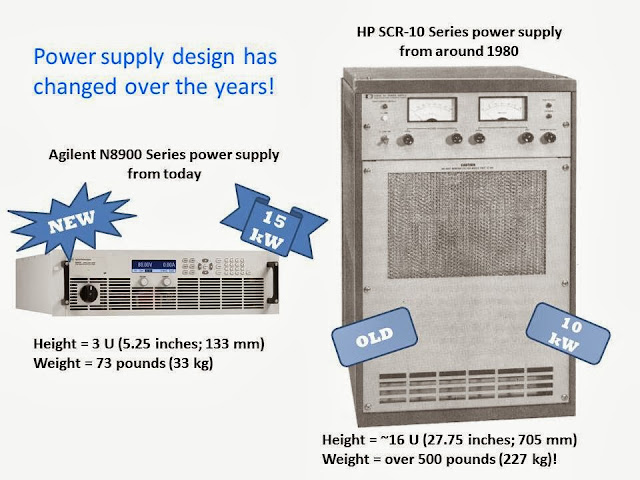
What is particularly exciting for us about the N8900 series of products is that it is the highest power level we have ever provided. I’ve been working here at Agilent with power products since 1980 (we were Hewlett-Packard back then and will soon get yet another new name), and until now, the highest-power power supply we offered was the HP SCR-10 Series at 10 kW. This product was discontinued many years ago. Now the new N8900 series has 5, 10, and 15 kW in a single model and outputs can be paralleled for 100 kW or more! Now that’s a lot of power!!

Back when I started, 10 kW came in a much larger package and weighed over 500 lb (227 kg)! Today, we can get 50% more power (15 kW total) in an 80% smaller package (3 U vs 16 U) that is 85% lighter (73 lb vs 500 lb). See the figure below.

The new N8900 series offers 14 different voltage, current, and power combinations with output voltages up to 1500 V and output currents up to 510 A. Outputs can be put in parallel for 100 kW or more. These are basic power supplies, but have autoranging output characteristics so you get more voltage and current combinations from a single output than if you used a power supply with a rectangular output characteristic. See the figure below.


For more information about autorangers and output characteristics, see the post I mentioned earlier (or click here.)

We also created a video introducing the N8900 series (I do a cameo toward the end…can you pick me out?).


These basic power supplies will be used in many different high-power applications, such as hybrid-electric vehicle test and photo-voltaic inverter test. So if you need a basic high-power power supply, check out the Agilent N8900 Series. And don’t hesitate to ask me a question about the product or its suitability for your application.
Thursday, September 12, 2013

How fundamental features of power supplies impact your test throughput – Part 2

In part 1 of” How fundamental features of DC power supplies impact your test throughput” (click here to access) I shared definitions of some of the fundamental power supply features that impact test throughput, including:
  • Command processing time
  • Up-programming response time
  • Down-programming response time


Another fundamental DC power supply feature impacting test throughput is its measurement time. There are actually two aspects to a DC power supply’s measurement time as depicted in Figure 1:
  • Measurement settling time
  • Measurement integration time


Figure 1: DC power supply measurement time

A good indicator of a DC power supply having a high performance measurement system is having programmable measurement integration time, or aperture time, often programmed in power line cycles (PLCs).  One reason for having a programmable integration time is for minimizing any 50 or 60 Hz AC line ripple getting into the DC measurement, by setting the time one or more multiples of a PLC.  Setting the time to 1 PLC provides good ripple rejection with relatively good throughput. When AC line ripple is not an issue the integration time can be set even smaller than 1 PLC, further reducing measurement time. When the DC power supply has a programmable measurement integration time it will no doubt also have a fast-responding measurement system as well, typically just milliseconds, to complement the higher achievable throughput with programmable measurement integration time.

In comparison basic DC power supplies commonly use a 100 millisecond fixed integration time to support AC ripple rejection for both 50 and 60 Hz line frequencies. They also have low bandwidth, slow-responding measurement systems, which can long time to settle after any step change in loading, before a valid measurement can be taken.

We have just introduced our Advanced Power System (APS) DC power supplies. This is a family of high-performance, high power (1 and 2 kW) DC power supplies designed to address the most demanding test challenges. These fundamental throughput-related features for APS are typically more than two orders of magnitude faster compared to more basic-performance DC power supplies, providing much better throughput in manufacturing test. A colleague of mine recently posted details of their introduction on his “General Purpose Electronic Test Equipment (GEPETE)” blog (click here to access) which I believe you will find of interest. Included in this introduction is a link on throughput that takes you to a series of application briefs I have written that go into more detail on improving test throughput with the DC power supply, which you may find very useful.


So how much test throughput improvement might you expect to see by switching from a basic-performance DC source to a high-performance DC source? Well, it really depends on how much the testing makes use of the DC power supply. If it only uses the power supply to provide a fixed DC bias to the device under test (DUT) that never changes for the duration of the test then it will not make a significant difference. More often than not however, a DUT is tested at several bias voltages with several current drain measurements taken for the various bias voltage settings and DUT operating modes. This can add up to a considerable amount of test time. In this case a high-performance DC power supply can more than pay for itself many times over due to improved test throughput.  To get an idea of the kind of difference a high-performance DC power supply can make I set up a representative benchmark test It compares the throughput performance one of our new APS DC power supplies to that of a more basic-performance power supply.  If you are interested in finding out how much difference it made, I made a video of this benchmark testing, entitled “Increasing Test Throughput with Advanced Power System” (click here to access). All I am going to say here is it is an impressive difference but you will need to watch the video to see how much difference!

Friday, September 6, 2013

How fundamental features of power supplies impact your test throughput – Part 1

When it comes to manufacturing of electronic products, reducing test time to improve throughput is virtually always a top priority, because “time is money” as the old saying goes! Usually most all of the attention may be placed on reducing the test time of the banner aspects of the product, such as the RF performance of a wireless device, for example. However, the choice of the DC system power supply can also have a huge impact on your test time and throughput during manufacturing. You may find the lowest cost, more basic-performance DC power supply that meets your immediate needs end up costing you the difference in price many, many times over of that of a higher-performance DC power supply having better throughput performance in the long run!

The DC power supply can incorporate a number of advanced features, such as elaborate triggering and sequencing systems, which will allow you restructure your testing to optimize throughput. However, even fundamental throughput-related features of the power supply can also have a large impact on your test time, including:
  • Command processing time
  • Output up-programming time
  • Output down-programming time
  • Measurement time

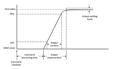
Figure 1 illustrates what the command processing and up-programming times are for a DC power supply. The command processing time is the time from when the command is first received to the point where the power supply starts acting on it. In this case it is when power supply’s output starts to change. The up-programming response time is the time the power supply takes for the output to rise and settle within a small band around the final output level, after processing the command instructing it to change its output level.


Figure 1: Power supply command processing and up-programming response times

The down-programming response time is like the up-programming response time except that the power supply is instead being programmed to a lower level. However, you need to look at down-programming independently as short up-programming time does not necessarily guarantee comparably short down-programming time. More basic performance DC power supplies usually lack an active down-programmer circuit that quickly brings down the output. In this case the down-programming response time can be very dependent on how much load the DUT presents to the power supply’s output.

How much difference is there in performance between more basic performance and higher performance DC power supplies on these throughput-related features? It can be considerable; over several orders of magnitude difference. As one example, command processing time can range from up to 100’s of milliseconds for entry-level power supplies to under 1 millisecond for high performance power supplies.
Another fundamental throughput-related feature of a DC power supply is its measurement time. There are a couple of aspects to consider here as well, which I will elaborate on in part 2 of this series on how fundamental features of power supplies impact your test throughput, in an upcoming posting here on “Watt’s Up?” along with tying it all together to show how they affect actual test throughput!

Saturday, August 31, 2013

Power Supply Programming: How Should I Send Commands to my Instrument

Hi everyone!  Happy Labor Day to all you readers in the US!  Every month I struggle with what I am going to write and wind up waiting till the end of the month to do my posting (and I am keeping that streak alive).  In order to combat that, I came up with a series of topics on programming instruments, focusing on our power supplies.  Let’s say that this is the first in a series of three (or maybe four I am not sure).  Please note that anything that I state here is my opinion and not Agilent policy.  Today I am going to focus on the how to send commands to your instrument.  In other words, what sort of IO library do you use to send the commands?

All of my suggestions will be based on the Agilent IO Libraries as that is the environment that I am most familiar with.  There are two major options: direct IO where you use the SCPI from the instrument and drivers where there are functions that you call.

First let’s talk about direct IO.  I learned how to program instrument using HPBASIC as my programming language so this is where it all began with me.  Agilent has two modern standards for doing this.  The first and the older standard is the VISA library.  VISA works very well when you are programming an instrument in the C programming language.  Here is a snippet of C code from a N6700 example with VISA (I have intentionally not provided comments to show the program in its purest form): 

VISAstatus=viOpenDefaultRM(&defrm);
VISAstatus=viOpen(defrm,”GPIB0::5”,VI_NULL,VI_NULL,&session);
viPrintf(session,"VOLT 5,(@1) \n");
viPrintf(session, "OUTP ON, (@1) \n");
viPrintf(session, "MEAS:VOLT? (@1) \n");
viScanf(session,"%s",&voltmeasurement);
viClose(session);
viClose(defrm);

It works pretty well and makes sense once you know it.  The viPrintf and viScanf functions are very similar to some basic C functions so if you are a C programmer, this is really the way to go.

There is also a newer option that works pretty nicely in languages that support COM.  This option is called Agilent VISA COM.  VISA COM works well in Visual Basic and C#.  Here is the same program to the above written in VB:

Set ioMgr = New AgilentRMLib.SRMCls
Set Instrument = New VisaComLib.FormattedIO488
Set Instrument.IO = ioMgr.Open("GPIB0::5")
Instrument.WriteString " VOLT 5,(@1)"
Instrument.WriteString " OUTP ON, (@1)”
Instrument.WriteString "MEAS:VOLT? (@1)”
Result = Instrument.Readstring
Instrument.IO.Close

In my opinion, this is easier to read than VISA.  When I have to write a program now, I tend to stick with using VISA COM and Visual Basic. 

The other option is to use a driver.  We presently offer two different driver types for our instruments: VXI Plug and Play and IVI COM.  VXI Plug and Play drivers are obsolete now though so I will not reference them further today.  Here is an example of our program using the IVI driver (in C#):

driver = new Agilent.AgilentN67xx.Interop.AgilentN67xx();
IAgilentN67xxProtection2 protectionPtr;
IAgilentN67xxMeasurement measurementPtr;
IAgilentN67xxOutput3 outputPtr;
int channel
driver.Initialize(“GPIB0::5”, idquery, reset, initOptions);
outputPtr = driver.Outputs.get_Item(driver.Outputs.get_Name(channel));
protectionPtr = driver.Protections.get_Item(driver.Protections.get_Name(channel));
measurementPtr = driver.Measurements.get_Item(driver.Measurements.get_Name(channel));
outputPtr.VoltageLevel(3.0, 3.0);
outputPtr.Enabled = true;
mVolt = measurementPtr.Measure(AgilentN67xxMeasurementTypeEnum.AgilentN67xxMeasurementVoltage);
driver.Close();

As you can see, the driver is much more complex than the direct IO examples. There are a few reasons to use a driver though.  The first and most common reason is that your system itself it designed to use drivers.  Another good reason is portability.  There are instrument classes in the IVI driver that should work for any DC power supply that is compatible.  One of the main downfall of our IVI drivers is that the functions almost always map 1 to 1 with SCPI so there are not many functions that work at a higher level and you don’t save any time programming there.

My main approach is to use VISA COM in Visual Basic.  I find it to be the easiest for me to program and it is what works for me.  Of course no opinion is wrong though and we are happy that our readers are out there buying and programming our instruments.  Thanks!


Tuesday, August 27, 2013

How to choose a Power Supply Part 1: Student Edition

Note from GaryR: We were fortunate to have an intern, Patrick, in our department for the summer. He has since returned to college, but during his time here at Agilent Technologies, he successfully completed several projects for us. During his last week, he wrote a power supply blog post! Here it is, unedited!!

Hello, I am Patrick, an intern here at Agilent Technologies. This is my first blog post but you might recognize me as “new intern… named Patrick” from the Matthew Carolan insta-classic, “What is Command Processing Time?” And as “Uncredited Waveform Capture Author” from GaryR’s visually-stunning, “Current Limit Setting Affects Voltage Response Time I might not be able to provide the same engineering life lessons Mr. Brorein, Mr. GaryR, and Mr. Carolan provide you monthly but hopefully you will enjoy this post nonetheless.

As you can probably tell from the title, this blog post is the first in a series written to help readers find the right DC power supply for them. For starters, there are a lot of other power supply companies out there; their products are not mentioned here. Actually, I better give you a disclaimer: this is an Agilent blog post about Agilent products written by an Agilent employee. However, my intentions in this post are to inform our readers on how to find a reliable and dependable power supply to the best of my abilities. I simply do not know enough about non-Agilent DC power supplies to be able to confidently recommend you any. With that out of the way, today’s post is written for college students, like myself, but can help give some insight to anyone looking for a power supply.

Agilent Technologies offers over 200 models of DC power supplies. Finding the perfect power supply for your needs is possible but can take some time. Fortunately, you have found your way to this blog post where I have already done all the work.

The first step in finding your power supply to buy is to determine your budget. If you are financially disabled like me, you are really lucky if you can save up $300 - $500 dollars between buying textbooks for a personal power supply. If you need convincing on why you make the expense, Matt’s “The Joys of Owning a DC Power Supply brings up some good points. Personally, I like being able to work where I want and when I want, including at my home during the summer where I would be lucky to find working batteries let alone a power supply. Also with the lifespan these power supplies have, this is a piece of equipment you will be using for decades. So first, figure out your budget!

The next thing to determine is what are you using this power supply for? Are you a hobbyist who only has low power needs? Do you need to power multiple DUTs at once for a senior project? Maybe you need a very precisely regulated and accurate output for a research project? If I wanted to work on labs outside of school I would need a supply with multiple outputs. If I wanted to work on side projects in my spare time my requirements are a lot simpler. Figure out what your performance requirements are, and try to anticipate future projects if you can.

Now, how much space do you have to work with? Power supplies come in many different sizes. In a test rack, a smaller power supply means more room for other test equipment. As a student you probably are not going to have a test rack, but you might have a test bench. If your test bench is anything like mine, it is also your laptop table, study space, dining area, and entertainment center. As you do before you buy a new couch, make sure you measure before you buy your new power supply.


For a student, here would be my priorities when shopping for a power supply: inexpensive, compact, and capable. All Agilent power supplies already provide low noise and well regulated outputs, so you do not have to worry about that. But keep in mind what functions and features you would like. For example, it would be nice to find one with an autoranging output characteristic, which would essentially allow one to perform the job of multiple, and/or a computer interface.

For those with similar priorities as above, shown in Table 1 are the power supplies that you might like. The table was populated with power supplies listed in our “Agilent Power Products Selection Guide”. The row on the top represents the base (no options) price range of the power supply if ordered from Agilent. The column on the left side represents your best choice in that price range. Keep in mind that the only difference in some budget ranges is the voltage/current ratings, which is important for your application but does not necessarily make one power supply better than the other. Within the table, each square states the model number of the power supply, voltage/current/power ratings, number of outputs, and number of ranges, available computer interfaces, and dimensions. The output ratings are sometimes separated by commas or there is another set listed below the first. If the power supply has multiple outputs, then each output is separated by a comma. If the power supply has multiple ranges, then each additional range is listed below the first.

To use Table 1, simply find your budget range and then match your application needs to the available models. Models in the same budget range but have increased functionality are placed higher.


The two families of power supplies that fall into the sub $1,000 price range are the E3600 and U8000 series basic power supplies. The E3600 gives you a lot of voltage/current choices, a number of outputs, as well as the ability to program with it in four of the options listed above. The U8000 is more limited in all these aspects but is more affordable and has features typically found only in programmable supplies such as OVP and OCP protection, recall states, and more. See for yourself how the E3600 and U8000 stack up against other power supplies.

All the power supplies listed above come in a ½ RU w x 2 RU h, with 1 RU being equivalent to 19” width and 1.75” height. This size is compact and will have no trouble fitting on a desk, and when not being used can easily be moved and stored.

It is unfortunate that there is no relatively inexpensive Agilent power supply with autoranging output characteristics. At least there are choices (within the E3600 series) with multiple ranges, giving you more output flexibility for more applications (learn more about rectangular vs. autoranging output characteristics).

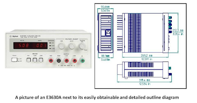
Also there is a three output power supply on the list (the E3630A) which is in the middle of the pack in terms of budget. The E3630A is actually the same power supply available at my school laboratories, able to handle every exercise I have done so far.

As a student, these power supplies might be outside your budget, but the least expensive choice, the U8001A, is about the same price as a Play Station 3. Would you rather choose: “fun” (the PS3) or “FUN!” (a power supply)? Please note that the distinguishing lowercase and uppercase variations of the word fun is not a reference to the level of fun but rather how loud I would yell it at you if we were face-to-face.

So, I have listed out your choices. All you have to do is figure out which one fits your applications. If you do not know what your applications are then you already missed a step in this blog post, so start over from the beginning. If you do not have an application then you probably do not need a power supply, but thank you for taking the time to read this. If you cannot find the right power supply for your application in this post then keep saving your money and look out for the next part on, “How to choose a DC power supply”, that is where the real fun starts. If you read this post and succeeded in choosing a power supply then awesome. Thanks for reading!


Thursday, August 15, 2013

Techniques for using the Agilent N6781A and N6782A and their seamless measurement ranging when currents exceed 3 amps

In an earlier posting “Zero-burden ammeter improves battery run-down and charge management testing of battery-powered devices” (click here to access) I had talked about how the Agilent N6781A 2-quadrant SMU can alternately be used as a zero-burden ammeter. When placed in the current path as a zero-burden ammeter, due to its extended seamless measurement ranging, it can measure currents from nanoamps, up to +/-3 amps, which is the maximum limit of the N6781A. The N6782A 2-quadrant SMU can also be used as a zero burden ammeter. It is basically the same as the N6781A but with a few less features.

One customer liked everything about the N6782A’s capabilities, but he had a battery-powered device that drew well over 3 amps when it was active. When in standby operation its current drain ranged back and forth between just microamps of sleep current to 6 or greater amps of current during periodic wake ups. The N6782A’s +/- 3 amps of current was not sufficient to meet their needs.

An alternate approach was taken that worked out well for this customer, which was made possible only because of the N6782A’s zero-burden ammeter capability. The set up is shown in Figure 1.


Figure 1: Setup for measuring micro-amps in combination with large active-state currents

The N6752A 50V, 10A, 100W autoranging DC power module provides all the power. The N6782A is set up as a zero-burden ammeter and is connected in series with the N6752A’s output. When current ranges from microamps up to +/- 3 amps the N6782A maintains its zero-burden ammeter operation, holding its output voltage at zero. Once +/- 3 amps is exceeded, the N6782A goes into current limit and the voltage increases across its output, at which point one of the back-to-back clamp diodes turns on, conducting current in excess of 3 amps through it. This all can be observed in the screen image of the 14585A software in Figure 2. The blue trace is the N752A’s output current. The middle yellow trace is the N6781A’s current and the top yellow trace is the N6781A’s voltage.


Figure 2: Current and voltage signals for Figure 1 setup captured with 14585A software

In Figure 2 measurement markers have been placed across a portion of the sleep current and we find from the N6782A’s measurement readback it is just 1.458 microamps average. The reason why this works is because of zero burden operation. Because the N6782A is maintaining zero volts across its output, there is no current flowing through either diode. If this same thing was attempted using a conventional ammeter or current shunt, the voltage would increase and current would flow through a diode, corrupting the measurement.

Now the customer was able to get the microamp sleep current readings from the N6782A and at the same time get the high level wake up current readings from the N6752A!

In a similar fashion another customer wanted to perform battery run down testing. Everything was excellent about using the N6781A in its zero-burden ammeter mode, along with using its independent DVM input for simultaneously logging the battery’s run down voltage in conjunction with the current. The only problem was they wanted to test a higher power device. At device turn-on, it would draw in excess of 3 amps, which is the current limit of the N6781A. Current limit would cause the N6781A to drop out of its zero-burden ammeter operation and in turn the device would shut back down due to low voltage. The solution was simple; add the back-to-back diodes across the N6781A acting as a zero-burden ammeter, as shown in Figure 3.  Any currents in excess of 3 amps would then pass through a diode. Schottky diodes were used so the device would momentarily see just a few tenths of a volt drop in the battery voltage, during the short peak current in excess of 3 amps. Now the customer was able to perform battery run-down testing using the N6781A along with the 14585A software to log all the results!


Figure 3: Agilent N6781A battery run-down test set up, with diode clamps for peak currents above 3A


Thursday, August 8, 2013

Zero-burden ammeter improves battery run-down and charge management testing of battery-powered devices

One way of assessing run-time of battery-powered devices is to power them up with a regulated DC source, place the device into its appropriate operating modes, and get the corresponding current drawn by the device for each of the various operating modes. Estimations of battery run-time can then be made for different user types, based on the percentage of time spent in each of these operating modes, and the capacity of the battery in mA-hours. The DC source must be able to maintain a stable, transient free voltage at the DUT. A lot of general purpose power supplies have difficulty with mobile wireless devices that draw fast rising, high peak currents. Providing the regulated DC source meets maintains a stable voltage, it offers some advantages, including:
  • Maintains a fixed voltage level over time, removing variability due to changing voltage.
  • Using built-in current read-back eliminates voltage drop issues encountered with using a resistive shunt. This is problematic with mobile wireless devices that draw high peak, but low average current.


An alternative to using a regulated DC source to power the battery powered device is instead use the actual battery. Just like with using a DC source, one can make representative current drain measurements over shorter periods for all the various operating modes and then make predictions on run-time. Alternately one can also perform actual battery run-down tests which, when performed correctly, yields quite a few more insights beyond representative current drain measurements, such as:
  • Low battery discharge termination details.
  • Battery capacity and energy actually delivered.
  • Actual run time achieved.
  • How well the battery and device work together as a system


An actual battery-run down test is an indispensable part of validation as a final proof of performance.

Just as with evaluating battery run-down, it is also just as important to evaluate battery charging and management. Again, a lot of testing can be done on a device independent of its battery, but there is also a lot of additional value in validating a device’s charge management performance with its actual battery.

When validating a device’s discharging and charging performance with an actual battery, the first test challenge is the current drawn from or sourced to the battery needs to be accurately measured and logged over time, together with the battery’s voltage, for making good capacity and energy measurements. The second test challenge here is you cannot afford to introduce any significant drop in voltage between the device and its battery, as this alters charging and discharging performance of the battery powered device. This can be a real problem when trying to use shunt resistors.

An alternative is to use a zero-burden ammeter. You may ask how an ammeter can be zero-burden. It has to have some resistance in order to produce a measurable value, right? Well, not always. Agilent provides an innovative alternative use of the N6781A 2-quadrant source measure module that enables it to operate as a zero-burden ammeter (in addition to being a DC source). Using the N6781A as a zero-burden ammeter to evaluate battery run-down and battery charging of a battery-powered device is depicted in Figure 1.


Figure 1: N6781A zero-burden ammeter / wattmeter operation

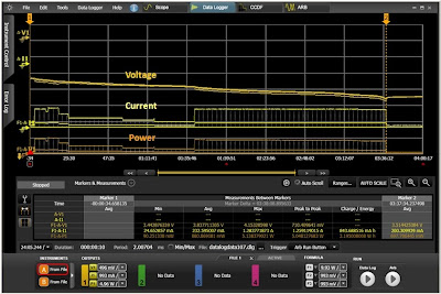
The N6781A is able to operate as a zero-burden ammeter because it is able to actively regulate its output at zero volts independent of the current flowing through it. Because its output is zero volts, when placed in series between the device and its battery, there is no voltage drop. At the same time its precision current measurement system is able to now measure the discharge or charge currents. In addition a separate voltage measurement port allows it to measure the battery voltage, so now you are able to capture the battery’s discharge or charge voltage profile, as well as determine charge in amp-hours and energy in watt-hours, as shown in Figure 2.


Figure 2: Capturing, displaying, and evaluating battery run-down results with 14585A software

A useful reference providing further details on evaluating a device’s battery run-down and charging, and how to configure and use the N6781A as a zero-burden ammeter are available in our application note; “Evaluating Battery Run-Down with the N6781A 2-Quadrant Source Measure Unit and the 14585A Control and Analysis Software” (click here to access).