Wednesday, July 30, 2014

How does power supply overvoltage protection work?

In past posts, I’ve written about what overvoltage protection (OVP) is (click here), where it is sensed (click here), and its history (click here). Today I want to cover a little about how it works inside the power supply.

As a quick review, OVP is a built-in power supply feature that protects the device under test (DUT) from excessive voltage by shutting down the power supply output if it senses voltage that exceeds the OVP setting. Depending on the power supply design, the voltage may be sensed at the output terminals or at the sense terminals.

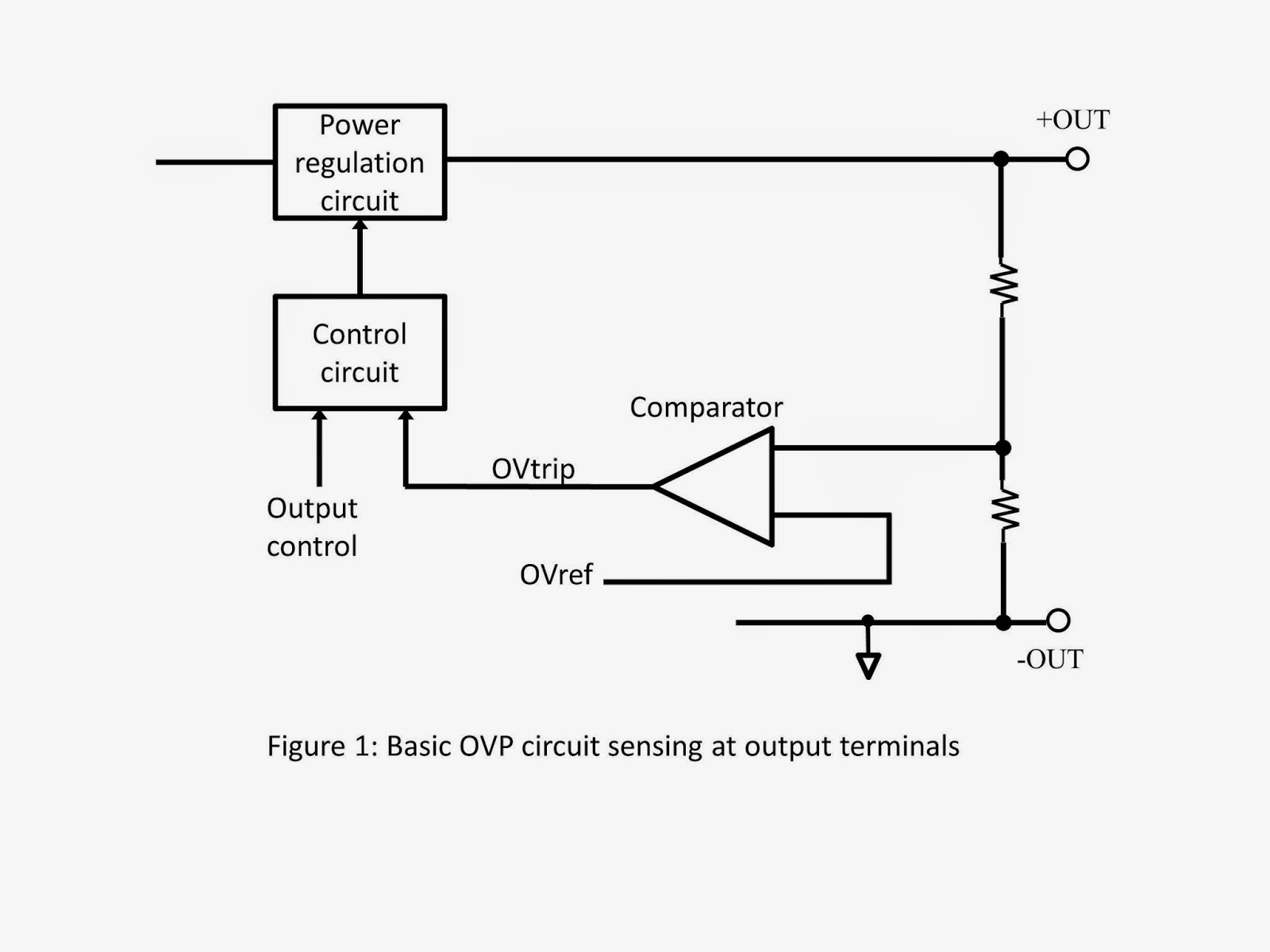
Most of Agilent’s older power supplies sense OVP at the output terminals and use a simple analog comparator circuit to determine when the output exceeds the OVP threshold set by the user. The OVP threshold is translated into an overvoltage reference voltage (OVref) that could come from a simple divider with a potentiometer for adjustment (uncalibrated and rather crude) or from a more sophisticated calibrated digital-to-analog converter (DAC) voltage. When the comparator sees the scaled output voltage exceed the OVref voltage, the overvoltage trip (OVtrip) signal is generated which shuts down the power supply output and, on some designs, fires an SCR across the output. See Figure 1 for a simplified representation of this arrangement.

Some of our newer designs look for an overvoltage condition on the sense terminals for better accuracy. In this scheme, the sense voltage feeds one comparator input through a differential amplifier while the other comparator input is driven by the user-set calibrated OVref voltage. See Figure 2. An output terminal OVP as described above must also be used as a backup with these designs (not shown in Figure 2) because some OV conditions are not caught when sensing OV on the sense terminals. For example, if the sense leads are shorted together, the output voltage will go up uncontrolled yet the sense voltage will remain at zero volts.

Some other OVP designs use a calibrated analog-to-digital converter (ADC) on either the output terminal voltage or the sense terminal voltage and compare the measured digital data to the user’s threshold setting. See Figure 3. To avoid nuisance OVP shutdowns, this scheme frequently requires several analog-to-digital conversions in a row exceed the threshold (for example, 4). This adds a minor delay to the OVP response time. With fast ADC conversion rates, the OVP response can still be just a few tens of microseconds and it is worth spending a little extra time to gain immunity against nuisance tripping. For example, the Agilent N6781A uses this technique. Since it does an ADC conversion every 5 us and requires 4 consecutive conversions exceed the OVP threshold to cause a shutdown, it will trip in less than 30 us.

So you can see that there are various ways to implement overvoltage protection. In all cases, rest assured that your DUT is protected against excessive voltage when using Agilent power supplies!

Tuesday, July 22, 2014

What does it mean when my Agilent power supply displays “Osc”?

When using certain higher performance power supplies from Agilent, like the N678xA series source-measure modules, you may discover that the output has shut down and an annunciator displaying “Osc” shows up on the front panel meter display, like that shown in Figure 1 for the N6705B DC Power Analyzer mainframe. 


Figure 1: DC Power Analyzer front panel meter displaying “Osc” on channel 1 output

As you would likely guess, Osc stands for oscillation and this means the output has been shut down for an oscillation fault detection. In this particular instance an N6781A high performance source measure module was installed in channel 1 of the N6705B DC Power Analyzer mainframe.

The N678xA series source measure modules have very high bandwidth so that they can provide faster transient response and output slew rates. However, when the bandwidth of the power supply is increased, its output stability becomes more dependent on the output wiring and DUT impedances. To provide this greater bandwidth and at the same time accommodate a wider range of DUTs on the N678xA modules, there are multiple compensation ranges to select from, based on the DUT’s input capacitance, as shown in the advanced source settings screen in Figure 2.


Figure 2: DC Power Analyzer front panel displaying advanced source settings for the N678xA

Note that “Low” compensation range supports the full range of DUT loading capacitance but this is the default range. While it provides the most robust stability, it does not have the faster response and better performance of the “High” compensation ranges.

As long as the wiring to the DUT is correctly configured and an appropriate compensation range is selected the output should be stable and not trip the oscillation protection system. In the event of conditions leading to an unstable condition, any detection of output oscillations starting up quickly shut down the output in the manner I captured in Figure 3. I did this by creating an instability by removing the load capacitance.


Figure 3: Oscillation protection being tripped as captured in companion 14585A software

In rare circumstances, such as with some DUTs drawing extremely high amplitude, high frequency load currents, which may lead to false tripping, the oscillation protection can be turned off, as shown in Figure 4.


Figure 4: N678xA oscillation protection disable in N6705B DC Power Analyzer advance protection screen

Oscillation protection is a useful mechanism that can protect your DUT and your power supply from an excessively high AC voltage and current due to unstable operating conditions. Now you know what it means next time you see “Osc” displayed on the front panel of you Agilent power supply and what you need to do to rectify it!

.

Monday, July 14, 2014

Extending the usable bandwidth of the DC source when performing AC disturbance testing on your DUT

A lot of various products that run off of DC power, often destined to be used in automobiles and other types of vehicles, but even quite a number in stationary applications as well, require validation testing for impact of having AC disturbances riding on top the DC powering them.

 Conducting this type of testing is often a big challenge for the test engineer in finding a solution that adequately addresses the disturbance test requirements. It usually requires multiple pieces of hardware:
  • A DC power supply is used to provide the DC bias voltage and power.
  • A power amplifier is used to generate the AC disturbance.
  • A separate ARB /function generator is needed to produce the reference signal for the disturbance

Coupling the DC power supply and power amplifier together is extremely problematic. While it would be great to just directly connect the two in series, this rarely can be done in practice as the power amplifier usually cannot handle the DC current of the power supply. A variety of custom approaches are then typically taken, all with their associated drawbacks.

An article about this very topic was published last year, written by a colleague I work with, Paul Young in our R&D group. As he noted it’s great when the power source can provide both the DC power as well as the AC disturbance as this is a big savings over trying to incorporate multiple pieces of equipment. Paul’s article “Extending the Usable Bandwidth of a Programmable Power Supply for Generating Sinusoidal Waveforms” (click here to review) is an excellent reference on this and the inspiration for my blog posting this week.

Our N6705B DC Power Analyzer in Figure 1 and recently introduced N7900A series Advanced Power System (APS) 1KW and 2KW power supplies in Figure 2 have proven to be very useful for doing a variety of testing where transients and audio disturbances are needing to be introduced on top of the DC that is powering the DUT.


Figure 1: Agilent N6705B DC Power Analyzer and N6700 series DC power modules


Figure 2: Agilent N7900A series 1KW and 2KW Advanced Power System and N7909A Power Dissipator

The reasons for these products being useful for disturbance testing are due to their built in ARB generation capability in conjunction with having a respectable AC bandwidth, on top of being able to source the DC power. Everything can be done within one piece of equipment.

A very common test need is to superimpose a sinusoidal disturbance in the audio range. One example of this is in automobiles. The alternator “whine” AC ripple induced on top of the DC output falls within this category. Our 1KW and 2KW N7900A series APS are good for applications needing higher DC power. However, at first glance the specified AC bandwidth of 2 kHz on does not look like it would work well for higher audio frequencies. The AC response of an N7951A from 1 kHz to 10 kHz is shown in Figure 3. This was captured using the 14585A companion software to set up its ARB.  There is noticeable roll off for higher frequency, as expected.


Figure 3: N7951A APS AC response characteristics captured using companion 14585A software

However, it’s worth noting that the roll off is gradual and very predictable. In the case of superimposing a relatively small AC signal on top of the DC output it is easy to compensate by measuring the attenuation at the given frequency and applying a gain factor to correct for it, as I did as shown in Figure 4. As one example, for 5 kHz, I programmed 2.38 volts peak to get the desired 1 volt peak.


Figure 4: N7951A APS AC response characteristics after gain correction

As can be seen it was simple to now get a flat response over the entire range. A limiting factor here is sum of the programmed DC value plus programmed AC peak value needs to be within the voltage programming range of the power supply being used. In practice, when the AC disturbance is reasonably small it is easy to cover a wide range of frequency.

Another factor to consider is capacitive loading. Some DC powered products sometimes have a fairly substantial filter capacitor built in across the DC power input. This will increase the peak current drain from the power supply when AC is applied on top of the DC. As an example a 100 microfarad capacitor will draw a peak current of 6.28 amps when a 10 kHz, 1 volt peak AC signal is applied. There may also be series impedance limiting the peak current, but whatever this AC peak current is it needs to be included when determining the size of the power supply needed.

With these basic considerations you will be able to perform AC disturbance testing over a much greater bandwidth as well!

.

Monday, June 30, 2014

Doing Inrush Current Testing with the New AC6800 AC Sources

Hi everybody,

It is the last day of the month and therefore time for me to get my blog post out.  I want to build on Gary's latest post concerning the new Agilent/Keysight AC6800 AC Sources (Click Here).  One of the key features that Gary mentioned is inrush current testing.

My colleague Russ did a video on inrush current testing for the launch.  This gives you a little bit of perspective on why you want to do the testing and gives some good tips.


When you do inrush current testing, you typically want the highest value that the current has reached when the power is enabled.  The AC6800 has a peak hold current value that will store this value for you.  The unit stores the highest current value it has measured since that value was last cleared (either manually or from power on).  One key thing to remember is to always clear out the peak hold value before doing your measurement so that you know that your measurement is up to date.

The AC6800 can synchronize the enabling of the output to a user defined phase.  When you specify the phase, it will enable the output at that phase in the sine wave (anything from 0 to 360 degrees).  The combination of the peak hold measurement and this phase synchronization are what make this testing possible.  

I  did a video for the launch where I did a tour of the front panel, including a short description of how to do inrush current testing:


I also have a programming example on this topic.  Below is a snippet of a program that I wrote in VB.NET using Agilent VISA-COM:


That's about it for me this month.  Please let us know if you have any questions in the comments.  


Monday, June 23, 2014

New Agilent Basic AC Power Sources

I have mentioned several times before that I avoid posting product-only-focused material in this blog, but when we announce something new, it is appropriate for me to mention it here. Today, a press release went out about our new AC sources (click here to view). You may not realize it, but this press release marks the end of an era; these are the last power products Agilent Technologies will ever announce! Now don’t go all non-linear on me…..I’m sure we will continue to design and release new power products for decades to come. But as I mentioned in a previous post (click here), as of August 1, 2014, our products will be Keysight Technologies products and not Agilent Technologies products. So these new AC sources will be rebranded to Keysight in a few weeks, but because we are releasing them before the company name change is official, we have to release them as Agilent and not Keysight. Go figure….

Anyway, what are these new Agilent (soon to be Keysight) AC sources? Well, the model numbers will remain the same through the company name change and they are:

  • AC6801A (500 VA)
  • AC6802A (1000 VA)
  • AC6803A (2000 VA)
  • AC6804A (4000 VA)

This new AC6800 Series of basic AC sources compliments our previous line of more sophisticated AC sources (click here for those) by adding lower cost models and higher power. Here is what the new series looks like (of course, the big one is the 4 kVA model):
All four new AC6800 models share these features:
  • Output capabilities
    • Single-phase output
    • 2 ranges: 0 to 135 Vrms; 0  to 270 Vrms
    • 40 Hz to 500 Hz and DC
    • Sine wave (other waveforms with analog interface)
  • Measurement capabilities
    • Vac, Vdc, Vrms
    • Iac, Idc, Irms, Ipeak, Ipeak&hold, crest factor
    • Watts, VA, VAR, power factor
  • Other
    • Universal AC input
    • LAN (LXI-Core), USB, optional GPIB
    • Optional analog programming interface
The differences in the models are due to the output power ratings and can be summarized by looking at the output characteristics when producing an AC output or a DC output:

For a DC output, the graph above shows only the positive voltage and current quadrant (first quadrant). The output is equally capable of putting out negative voltage and negative current (the third quadrant) and the ratings are the same (except negative). These AC sources only source power; they cannot sink (absorb) power.

These AC sources do have one advanced feature: you can set the phase angle at which the output turns on. Coupled with the ability to measure peak current (and hold the peak current measurement), this is good for AC inrush current measurements.
To view the data sheet, click here.

So that’s the new line of basic AC power sources from Agilent and the last power products to be announced by Agilent. I wonder when the first Keysight power product announcement will be…..wouldn’t you like to know!?!?

Safeguarding your power-sensitive DUTs from an over power condition

Today’s system DC power supplies incorporate quite a variety of features to protect both the device under test (DUT) as well as the power supply itself from damage due to a fault condition or setting mishap. Over voltage protect (OVP) and over current protect (OCP) are two core protection features that are found on most all system DC power supplies to help protect against power-related damage.

OVP helps assure the DUT is protected against power-related damage in the event voltage rises above an acceptable range of operation. As over voltage damage is almost instantaneous the OVP level is set at reasonable margin below this level to be effective, yet is suitably higher than maximum expected DUT operating voltage so that any transient voltages do not cause false tripping. Causes of OV conditions are often external to the DUT.

OCP helps assure the DUT is protected against power-related damage in the event it fails in some fashion causing excess current, such as an internal short or some other type of failure. The DUT can also draw excess current from consuming excess power due to overloading or internal problem causing inefficient operation and excessive internal power dissipation.

OVP and OCP are depicted in Figure 1 below for an example DUT that operates at a set voltage level of 48V, within a few percent, and uses about 450W of power. In this case the OVP and OCP levels are set at about 10% higher to safeguard the DUT.


Figure 1: OVP and OCP settings to safeguard an example DUT

However, not all DUTs operate over as limited a range as depicted in Figure 1. Consider for example many, if not most all DC to DC converters operate over a wide range of voltage while using relatively constant power. Similarly many devices incorporate DC to DC converters to give them an extended range of input voltage operation. To illustrate with an example, consider a DC to DC converter that operates from 24 to 48 volts and runs at 225W is shown in Figure 2. DC to DC converters operate very efficiency so they dissipate a small amount of power and the rest is transferred to the load. If there is a problem with the DC to DC converter causing it to run inefficiently it could be quickly damaged due to overheating. While the fixed OCP level depicted here will also adequately protect it for over power at 24 volts, as can be seen it does not work well to protect the DUT for over power at higher voltage levels.


Figure 2: Example DC to DC converter input V and I operating range

A preferable alternative would instead be to have an over power protection limit, as depicted in Figure 3. This would provide an adequate safeguard regardless of input voltage setting.


Figure 3: Example DC to DC converter input V and I operating range with over power protect

As an over power level setting is not a feature that is commonly found in system DC power supplies, this would then mean having to change the OCP level for each voltage setting change, which may not be convenient or desirable, or in some cases practical to do. However, in the Agilent N6900A and N7900A Advance Power System DC power supplies it is possible to continually sense the output power level in the configurable smart triggering system. This can in turn be used to create a logical expression to use the output power level to trigger an output protect shutdown. This is depicted in Figure 4, using the N7906A software utility to graphically configure this logical expression and then download it into the Advance Power System DC power supply. As the smart triggering system operates at hardware speeds within the instrument it is fast-responding, an important consideration for implementing protection mechanisms.


Figure 4: N7906A Software utility graphically configuring an over power protect shutdown

A glitch delay was also added to prevent false triggers due to temporary peaks of power being drawn by the DUT during transient events. While the output power level is being used here to trigger a fault shutdown it could have been just as easily used to trigger a variety of other actions as well.

Tuesday, June 3, 2014

Upcoming Webinar on High Power Source/Sink Solutions for Testing Bidirectional Energy Devices

Bidirectional and regenerative energy devices both source and sink power and energy. Correspondingly, a solution that can both source and sink power and energy is needed for properly testing them. In the past here on “Watt’s up?” we have talked about what two and four quadrant operation is in our posting “What is bipolar four quadrant power? (Click here to review). We have also talked about cross over behavior between sourcing and sinking current with a DC source that will operate in two quadrants in a two-part posting  “Power supply current source-to-sink crossover characteristics” (Click here to review pt. 1) and (Click here to review pt. 2). These give useful insights about the nature of multi-quadrant solutions for bi-directional test applications.


Figure 1: The four operating quadrants

Bidirectional and regenerative energy devices that are used in many applications, such as satellite power systems, alternative energy, automotive, and many other areas, operate at kilowatt and higher power levels. These higher power levels have a significant impact on solutions and approaches taken to address their testing.  Also, the nature of these bidirectional and regenerative energy devices are not all the same. This also has an impact in that the capabilities of the test solutions need to be different to address these different types of devices.

In my upcoming webinar on June 18th, titled “Conquering the High Power Source/Sink Test Challenge” I will be exploring the test needs of key bidirectional and regenerative energy devices and then go into the details of various test solutions and approaches for sourcing and sinking power and energy, along with their associated advantages and disadvantages. This is just a couple of weeks away. So if you are involved in this kind of work and are interested, or would just like to learn more, you can register online at the following (click here).  In case you cannot join the live event you will still be able to register and listen to seminar afterward instead, as it will be recorded.  I hope you can join in!


.