Showing posts sorted by relevance for query floating. Sort by date Show all posts

Friday, March 28, 2014

What is a floating power supply output?

First let me tell you that a floating power supply output is NOT what is shown below in Figure 1 (haha).


Now some background: earth ground is the voltage potential of the earth and to greatly reduce the risk of subjecting a person to an electrical shock, the outer covering (chassis) of most electrical devices is internally connected to a wire that is connected to earth ground usually through the power cord. The idea here is to ensure that all surfaces a person can touch are at the same voltage potential; namely, the one that he is standing on: earth ground. As long as that is true, the person can freely touch things without the risk of getting shocked due to two of the things he touches at the same time being at different voltage potentials, or one of the things being at a high voltage potential with respect to the earth. If the voltage difference is high enough, the person could be shocked. Earth grounding the chassis also protects the user if there is an internal problem with an electrical device causing its chassis to inadvertently come in contact with an internal high voltage wire. Since the chassis is earth grounded, an internal short to the chassis is really a short to ground and will blow a fuse or trip a circuit breaker to protect the user instead of putting the chassis at the high voltage. If you touched a chassis that had a high voltage with respect to ground on it, your body completes the path to ground and you get shocked!

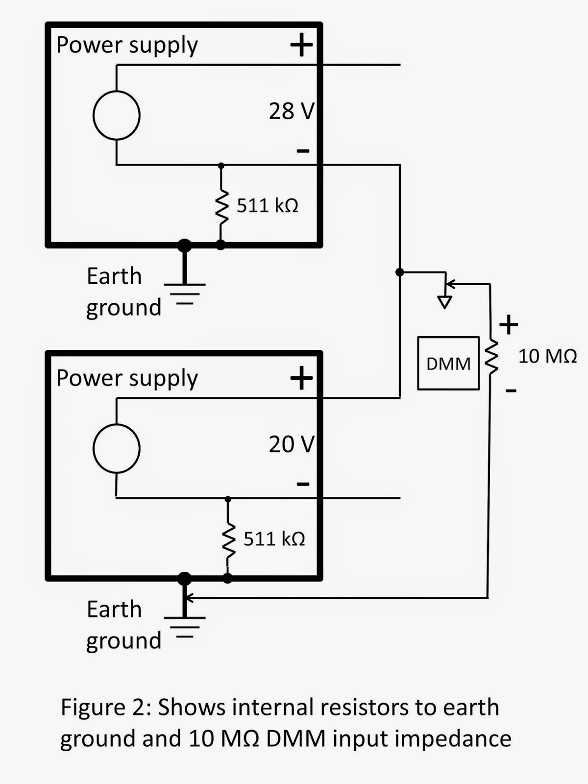
So to protect the user (and for some other reasons), the chassis of Agilent power supplies are grounded internally through the ground wire (the third wire) in the AC input line cord. Additionally, most if not all of our Agilent power supplies have isolated (floating) outputs. That means that neither the positive output terminal nor the negative output terminal is connected to earth (chassis) ground. See Figure 2.


Figure 3 shows an example of non-floating outputs with the negative output terminal grounded.


For floating DC power supplies, the voltage potential appears from the positive output terminal to the negative output terminal. There is no voltage potential (at least, none with any power behind it) from either the positive terminal to earth ground or from the negative output terminal to earth ground. A power supply with a floating output is more flexible since, if desired, either the positive or negative terminal (or neither) can be connected to earth ground. Some devices under test (DUT) have a DC input with either the positive or negative input terminal connected to earth ground. If one of the power supply outputs was also internally connected to earth ground, when connected to the DUT, it could short out the power supply output. So power supplies with floating output terminals (no connections to earth ground) are more versatile.

If the outputs are floating from earth ground, we need to specify how far above or below earth ground you can float the output terminals. Our power supply documentation provides this information. For example, most Agilent power supply output terminals can float to +/-240 Vdc off of ground. You will frequently see the following in our documentation:


Also, some power supplies have different float ratings for the positive and negative output terminals. For example, for Agilent N5700 models rated for more than 60 Vdc, the following note in the manual means you can float the positive output terminal up to +/-600 Vdc from ground or the negative output terminal up to +/-400 Vdc from ground:


The output characteristic table may list this as “Output Terminal Isolation” as shown below which means the same thing as maximum float voltage:


Figure 4 shows an example of floating a power supply to 200 V above ground. The power supply output is set to 40 V.


You can see from the last example that you have to take the power supply output voltage into consideration when ensuring you are not violating the float voltage rating. If you exceed the float voltage rating of the power supply, you are potentially exceeding the voltage rating of internal parts that could cause the internal parts to fail or break down and present a shock hazard, so don’t violate the float voltage rating!

Saturday, November 29, 2014

Why do I measure voltage to earth ground on a power supply with a floating output?

Occasionally, one of our power supply users contacts us with a question about voltages measured from one of the power supply output terminals to earth ground (same as chassis ground). All of our power supply outputs are floating with respect to earth ground. See my previous post about this here. In that post, I stated that neither output terminal is connected to earth ground. To be more specific, no output terminal is connected directly to earth ground. We do have internal components, mainly resistors and capacitors, connected from each output terminal to earth ground. These components, especially the caps to ground, help mitigate issues with RFI (radio-frequency interference) and ESD (electrostatic discharge). They help prevent our power supplies from being susceptible to externally generated RFI and ESD, and also help to reduce or eliminate any internally generated RFI from being conducted to wires connected to the output terminals thereby reducing RFI emissions.

So even though our outputs are considered floating with respect to earth ground, there frequently is a DC path from at least one of our output terminals to earth ground. It is typically a very high value resistor, such as several megohms, but could be as low as 0.5 MΩ. This resistor acts as a bleed resistor to discharge any RFI or ESD caps to earth ground that could be charged to a high float voltage.

As an example of a power supply with a resistor to earth ground, the Keysight N6743A has 511 kΩ (~0.5 M) from the minus output terminal to earth ground. This resistor was responsible for the voltage measurements to earth ground observed and questioned by one of our power supply users. He was using this power supply in the configuration shown in Figure 1 and measured 9.7 Vdc from his common reference point to earth ground (again, same as chassis ground).


He understandably did not expect to measure any stable voltage between these points given that the output terminals are floating from earth ground. But once we explained the high impedance DC path from the minus output terminal to earth ground inside each power supply (see Figure 2), and the 10 MΩ input impedance of his DMM, the measurement made sense. The input impedance of the voltmeter (DMM) must be considered to accurately calculate the measured voltage. This is especially true when high impedance resistors are in the circuit to be measured.


Figure 3 shows the equivalent circuit which is just a resistor divider accounting for the 9.7 V measurement. (The exact calculation results in 9.751 V.) Notice that the voltage of the 28 V power supply does not impact this particular voltage measurement (but its resistor to ground does). If the user had measured the voltage from the plus output of the 28 V power supply to earth ground, both the 28 V supply and 20 V supply would have contributed to his measurement which calculates out to be 37.05 V (if you check this yourself, don’t forget to move the 10 MΩ resistor accounting for the different placement of the DMM impedance).


So you can see that even with power supply output terminals that are considered floating, there can still be a DC path to earth ground inside the supply that will cause you to measure voltages from the floating terminals to ground. As one of my colleagues always said, “There are no mysteries in electronics!”

Thursday, April 30, 2015

When is a number not a number?

All of our power supplies measure their own output voltage and output current. These measured values are available to you from the front panel and over the bus. They may be displayed as an average value or a digitized waveform. Some products have different measurement ranges you can set that affect the accuracy of the measurement and the noise floor of the measurement. Of course, there is a maximum value that each measurement range is capable of measuring. So what happens to the reading if the actual output voltage or current exceeds the maximum value of the measurement range? What does the front panel show and what value do you get if you read it back over the bus?

Below is an example where I set the current measurement range to the 1 mA range on a Keysight N6781A Source/Measure Unit. I then forced more than 1 mA to flow out of the output. As you can see, the front panel indicates “Overload”. If you perform a current measurement and read the result back to your PC, you will get 9.91E37. This is a value defined in the SCPI (Standard Commands for Programmable Instruments) standard to mean “not a number” (NAN). Since Keysight products follow the SCPI standard, we return this number when a range is overloaded. This numeric value for NAN was chosen so that it can be represented as a 32-bit floating point number and is larger than anything expected to occur while using instrumentation. In addition to an overload condition on an instrument, NAN can also be used as the result when, for example, you divide zero by zero or subtract infinity from infinity.
This predefined number is also used when waveform data exceeds the maximum rating of a particular range. The screenshot below on the left shows data that does not overload the range. But when the range is changed and part of the waveform exceeds the maximum rating of the range, that part of the waveform data shows up on the screen in red and when returned to a PC, the value is the NAN value of 9.91E37.

Two other unique numbers defined by the SCPI standard are used to represent positive infinity and negative infinity. For positive infinity (INF), 9.9E37 is used. For negative infinity (NINF), -9.9E37 is used. These values can be used to mean “maximum” for a setting. For example, our output voltage slew rate setting has a range of values to which it can be set. If you want to ensure the output voltage will change as quickly as possible, you want to set this to the maximum slew rate possible. Instead of looking up the specification for the maximum setting, you can use the appropriate SCPI command to set the slew rate to 9.9E37 and it will go to the maximum possible slew rate.

So when is a number not a number? When it is equal to 9.91E37!

Wednesday, November 21, 2012

How can I get more power from my power supplies?

If you need more voltage than one of your power supply outputs can provide, you can put power supply outputs in series to increase the total voltage. If you need more current than one of your power supply outputs can provide, you can put power supply outputs in parallel to increase the total current. However, you do have to take some precautions with series or parallel configurations.

Precautions for series connections for higher voltage:
  • Never exceed the floating voltage rating (output terminal isolation) of any of the outputs
  • Never subject any of the power supply outputs to a reverse voltage
  • Connect in series only outputs that have identical voltage and current ratings
Precautions for parallel connections for higher current:
  •  In most applications, one output must operate in constant voltage (CV) mode and the other(s) in constant current (CC) mode
  •  In most applications, the load on the output must draw enough current to keep the CC output(s) in CC mode
  • Connect in parallel only outputs that have identical voltage and current ratings

You can use remote sensing with either a series or parallel configuration. Figure 1 shows remote sensing for series outputs and Figure 2 shows remote sensing for parallel outputs.


You can find more information about power supply series and parallel configurations in an Agilent document called “Ten Fundamentals You Need to Know About Your DC Power Supply” by clicking on this link:
Refer to tip number 4 on page 6. This document also covers nine other useful power supply fundamentals.