Showing posts with label power supply. Show all posts

Wednesday, September 2, 2015

Yet another new Keysight power product family - this time, compact bench-top DC power!

Last week, I posted about our new photovoltaic (PV) array simulators, models N8937APV and N8957APV. These power supplies can produce an I-V curve as their output characteristic and provide up to 15 kW, 1500 V, and 30 A. Today, I am posting about yet another new series of Keysight power products (wow, our R&D team has been busy!). This new family is at the opposite end of the power spectrum compared to the 15 kW PV array simulators. The new family consists of five models in the 30 to 40 W range with voltages up to 100 V and currents up to 5 A all providing a standard rectangular output characteristic. Click here for the press release that just went out yesterday!

I really like this new family of power supplies and I think you will too!

Why?

Because….

You can choose from a variety of voltage and current combinations to meet your needs.

You can save space on your bench with these very compact models that are only 2U high and ¼-rack-width wide.

You can set and read back very accurate voltage and current values with a basic accuracy of 0.05%.

You can view the high visibility OLED display from nearly any angle.

You can regulate your set voltage at your load to make up for voltage drop in your load leads with remote sense terminals and leads.

You can communicate with these power supplies with either LAN or USB since both interfaces are included.

You can protect your device under test with the built in overvoltage protection and overcurrent protection.

And you can easily access all of the other beneficial features in this tiny package with the on-screen menu system.

So you can see that there is a lot you can do with these compact power packages!

Here is a listing of the models:
Below is a picture of the family showing each of the five new models.
So the next time you have to equip your bench with DC power that goes beyond a basic power supply, consider the new E36100 Series Programmable DC Power Supplies from Keysight Technologies. I know I would (but then again…..look where I work…..)!

Thursday, July 30, 2015

How do I use Python (and no installed IO Library) to talk to my instrument?

Hello everybody,

Our newest support engineer and I have decided to learn Python (https://www.python.org/) so that we can generate programming examples.  We are hearing that more and more customers are using Python so we figured that we would get on the front side and learn some Python.  This blog represents my first attempts at doing anything in Python so there are probably better methods to do this but I wanted to get this out since I am pretty excited about it.  

What we are going to do is do use Python with Telnet and LAN to directly send SCPI commands to my instrument.  The major advantage of this is that with this method, you do not need to use an IO Library so you can use it in different operating systems.  Since we are going to be using Telnet with Python, the first thing that we are going to need to do is to make sure we understand how telnet works with our power supplies.  For all my work here, I will be using my N7953A Advanced Power System (APS) because it is on my desk and it is awesome.  The APS uses port 5024 for telnet.  On my PC running Windows 7, I enter the following in my command window:

Figure 1


Once I hit enter, I get our very friendly welcome screen:
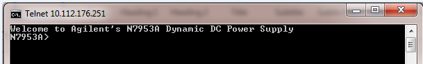
Figure 2


Note the text “Welcome to …”, this will be important later.

To send commands or do queries, you just need to enter the SCPI command after the prompt.   The response to the query will automatically appear after you hit "Enter".  Here is how you do a *IDN? Query:

Figure 3


Note that the query response ends with a new line.  This will be important later.  The prompt also re-appears after every interaction.  In the case of the APS, the prompt is the model number ("N7953A>").  On some other instruments , the prompt is "SCPI>".  Either way, you need to know what the prompt is so that you can account for it later.

 Now that we are Telnet experts, we are going to switch to Python and send a *IDN? query to my APS.  The first thing we are going to do is to import the telnet library.  After that we are going to create our APS object by opening a telnet session to the instrument (sorry these screenshots might overflow the frame a very tiny bit):
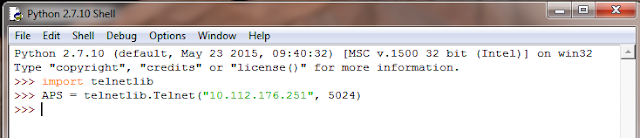
Figure 4


Basically, we are at the same point we are at in Figure 1.  We essentially just hit the "Enter" key.  We need to get to the equivalent to Figure 2 so that we can send a command.  That means that we need to read out all of that welcome text from the power supply.  Luckily, the Python Telnet Library has a read_until function that will read text until it encounters a predefined string.  We know that our prompt to enter text in this case is "N6753A>" so that is what we are going to use:


Figure 5

Let’s send our *IDN? query.  You use the write command to write to the Telnet session.  Helpful tip: all commands sent through telnet need to be terminated with a newline ("\n"):

Figure 6

So now that we sent a query, we need to read the buffer to get the response.  Remember that the query response ends with a newline so we are going to use read_until and use the newline ("\n") as our read_until text:

Figure 7


As you can see we get the same response as before.

So now we sent our command and read the response, we need to read out the prompt again so that our power supply is ready to accept the next command sent to it.  We will just use the same read_until that we used before:

Figure 8


Now we are set to send the next command.

When you are done with programming the instrument, you end the Telnet session with the close command:

Figure 9


So that's an extremely basic example of how to use Python and Telnet.  I used the shell because that is what I used to figure this all out.  You can also write scripts.  As Chris and I learn more about Python, we will be releasing more examples.  Stay tuned for those.


Saturday, November 29, 2014

Why do I measure voltage to earth ground on a power supply with a floating output?

Occasionally, one of our power supply users contacts us with a question about voltages measured from one of the power supply output terminals to earth ground (same as chassis ground). All of our power supply outputs are floating with respect to earth ground. See my previous post about this here. In that post, I stated that neither output terminal is connected to earth ground. To be more specific, no output terminal is connected directly to earth ground. We do have internal components, mainly resistors and capacitors, connected from each output terminal to earth ground. These components, especially the caps to ground, help mitigate issues with RFI (radio-frequency interference) and ESD (electrostatic discharge). They help prevent our power supplies from being susceptible to externally generated RFI and ESD, and also help to reduce or eliminate any internally generated RFI from being conducted to wires connected to the output terminals thereby reducing RFI emissions.

So even though our outputs are considered floating with respect to earth ground, there frequently is a DC path from at least one of our output terminals to earth ground. It is typically a very high value resistor, such as several megohms, but could be as low as 0.5 MΩ. This resistor acts as a bleed resistor to discharge any RFI or ESD caps to earth ground that could be charged to a high float voltage.

As an example of a power supply with a resistor to earth ground, the Keysight N6743A has 511 kΩ (~0.5 M) from the minus output terminal to earth ground. This resistor was responsible for the voltage measurements to earth ground observed and questioned by one of our power supply users. He was using this power supply in the configuration shown in Figure 1 and measured 9.7 Vdc from his common reference point to earth ground (again, same as chassis ground).


He understandably did not expect to measure any stable voltage between these points given that the output terminals are floating from earth ground. But once we explained the high impedance DC path from the minus output terminal to earth ground inside each power supply (see Figure 2), and the 10 MΩ input impedance of his DMM, the measurement made sense. The input impedance of the voltmeter (DMM) must be considered to accurately calculate the measured voltage. This is especially true when high impedance resistors are in the circuit to be measured.


Figure 3 shows the equivalent circuit which is just a resistor divider accounting for the 9.7 V measurement. (The exact calculation results in 9.751 V.) Notice that the voltage of the 28 V power supply does not impact this particular voltage measurement (but its resistor to ground does). If the user had measured the voltage from the plus output of the 28 V power supply to earth ground, both the 28 V supply and 20 V supply would have contributed to his measurement which calculates out to be 37.05 V (if you check this yourself, don’t forget to move the 10 MΩ resistor accounting for the different placement of the DMM impedance).


So you can see that even with power supply output terminals that are considered floating, there can still be a DC path to earth ground inside the supply that will cause you to measure voltages from the floating terminals to ground. As one of my colleagues always said, “There are no mysteries in electronics!”

Monday, November 24, 2014

Prewired rack delivers up to 90 kW of single-output DC power

As I have mentioned before, I avoid posting product-only-focused material in this blog since our goal is to educate about power-related items rather than to directly promote Keysight products. But when something new comes out, I like to announcement it here.

A little over a year ago, Keysight (we were Agilent at the time) announced a new power supply family with high-power outputs up to 15 kW per output (see link here). These high-power autoranging DC power supplies with individual outputs up to 1500 V or 510 A can be paralleled for even more power. Paralleling outputs with these supplies is simplified since multiple outputs can be grouped to act as a single output and the current share bus enables multiple outputs to more equally share current. But there are other considerations when paralleling multiple units. Wiring the AC inputs and DC outputs together takes design time and assembly time. Integrating the units together physically in a rack also takes time and effort. Designing the system to ensure the safety of operators is also very important. So Keysight decided to offer a prewired rack to help you overcome the challenges associated with racking high-power supplies.

On November 11, 2014 (less than 2 weeks ago), we announced a prewired rack that combines up to six of the 15 kW N8900 series power supplies for total power up to 90 kW from a single output. You can choose from a variety of DC output combinations with voltages from 80 V to 1500 V and currents from 60 A to 3060 A. That’s a lot of current! The rack’s internal configuration makes the multiple outputs appear as a single output allowing you to communicate with just one power supply through LAN, GPIB, or USB (all standard in the system). Click here for the press release for this new system and here for additional system information.


Perhaps you are working in R&D or manufacturing on EV/HEV, alternative energy (fuel cells, solar, etc.), industrial DC motors, large UPS’s, electroplating, or any of the many other high-power application areas that need DC power up to 90 kW with voltages to 1500 V or currents to 3060 A. If so, and you want to spend your engineering resources on your core competencies instead of racking power supplies together, let Keysight help you with our new N8900 Series Rack System.

Thursday, October 30, 2014

What is a reverse protection diode and what does it do?

A reverse protection diode is used on the output of a power supply to protect the power supply from damage due to an externally applied reverse voltage. Most power supplies have a polarized electrolytic capacitor (or several) across the output terminals. These caps help to filter ripple and noise on the output and provide a charge reservoir to reduce voltage sags and surges due to large load current changes. Electrolytic caps can withstand some reverse voltage, but not much. About 1 V to 1.5 V is the most they will tolerate without venting or worse…exploding! The reverse protection diode limits the reverse voltage to a diode drop thereby protecting the output caps. The diode is typically rated for the full output current of the power supply it is protecting. Adding to the diode drop, there can be some more small voltage drops due to current flowing in wires, tracks, current monitor resistors, output filter inductors, switching transformer windings, etc.

In a linearly regulated power supply, the reverse protection diode must be added to the design with the cathode connected to the plus output and anode connected to the minus output. See Figure 1. In a switching power supply, the reverse protection diode(s) is (are) an inherent part of the design. See Figure 2.


But where does reverse voltage come from? During normal operation, reverse voltage does not occur on the output of a power supply (unless it is a bipolar power supply which does not use polarized caps on its output…see this post). The power supply internal circuitry typically cannot produce reverse voltage on the output even if a failure occurs inside the power supply. So a reverse voltage has to be applied from an external source of power. For example, if you use two power supply outputs in parallel and inadvertently connect them to each other backwards, a reverse voltage would result. Another possibility can occur when two power supply outputs are connected in series. If the load across the series combination shorts, the two power supply outputs will be connected to each other backwards. See Figures 3 and 4. The reverse protection diode of one of the power supplies will conduct all available current from the other power supply forcing it into constant current (CC) operation and limiting the voltage to a diode drop (plus any additional small drops mentioned above).


So rest assured that your Keysight power supply is protected against reverse voltage if something unexpected happens!

Monday, September 29, 2014

Properly sequence multiple power inputs to protect your DUT

As I mentioned in a previous post, we have devoted a lot of time writing about protecting your device under test (DUT) from the two main DUT-destroying forces available from a power supply: excessive voltage and excessive current. Click here for one of the latest posts including a list to the other posts.

Today I’d like to cover another topic that can cause DUT failure due to a power supply. Some DUTs have multiple DC inputs and some of these multiple-input DUTs are sensitive to the order in which the inputs turn on or turn off. Subjecting the device to an uncontrolled sequence could cause latch-up or excessive current to flow resulting in compromised reliability or even immediate catastrophic failure of the DUT. So properly sequencing the multiple voltages at turn on and off is essential. My colleague, Ed Brorein, wrote a very similar post last year (click here) but I thought this topic was worth repeating especially since we added another series of power products with higher power that has this capability.

Various methods have been used in an effort to address the potential problem associated with improperly sequenced power inputs. Diodes can be placed from one input to another to clamp the voltage thereby preventing one input voltage from going too far above or below another input voltage but this method has limited effectiveness and variable results. Relays can be put in series with each input and controlled with timing circuitry but the relays introduce variable series impedance and timing is imprecise. FETs with associated control circuitry can be placed in series with each input however this method requires significant design time and adds complexity to the setup. Multiple DC power supplies can be controlled through software, but once again, timing is imprecise and response times can be slow.

Several years ago, I wrote an application note on a closely related topic (click here). The method that is most precise and introduces the fewest complications is to use a power supply system that has output sequencing integrated into the system itself. Keysight has several power supply systems that can accommodate precise output sequencing: the N6700 Modular Power System, N6705 DC Power Analyzer, and the more recently released N6900/N7900 Advance Power System. Each system offers the ability to precisely control the turn-on and turn-off sequence of multiple outputs. Timing is set with sub-millisecond resolution. Synchronization across systems is also possible to facilitate timed shut downs of larger numbers of power supply outputs for your DUT inputs. The above mentioned application note specifically addressed the topic of how to configure the system to properly shut down your DC inputs in sequence upon a fault generated by any of the system power supplies.

Below is a simple example of a sequenced turn on of four outputs in an N6705B mainframe. The sequencing is facilitated by setting a different turn-on delay time for each of the outputs (turn-off delays can be set independently). When all outputs are told to turn on simultaneously, the delays are activated resulting in a precisely controlled sequenced turn on. Figure 1 shows how easy it is to implement the delays for a turn-on event. In this case, I used four power supply outputs in an N6705B mainframe with delays set to 5 ms, 10 ms, 15 ms, and 20 ms. I set the output voltages to 10 V, 7.5 V, 5 V, and 3.3 V. You can also set the output voltage rise time (slew rate) independently for each output. Figure 2 shows the results using the scope that is built into the N6705B mainframe.


So you can see that with the proper power supply system, sequencing your multiple DC power supply inputs on your device to protect it from damage is easy. Keysight provides you with the solution to do just that adding to our arsenal of features that protect your valuable DUT.

Thursday, August 28, 2014

What can cause a power supply output voltage to exceed its setting?

We have done a number of posts on power supply protection topics covering both voltage and current issues:

Safeguarding your power-sensitive DUTs from an over power condition

How does power supply overvoltage protection work? 

Protect your DUT from over-current in more ways than one

What is a power supply’s over current protect (OCP) and how does it work?

Overvoltage protection: some background and history

Protect your DUT: use sense leads for overvoltage protection (OVP)

Types of current limits for over-current protection on DC power supplies

Protect your DUT with power supply features including a watchdog timer

And just last week, on August 20, 2014, my colleague and fellow Watt’s Up? blog contributor, Ed Brorein, presented a live webcast called “Protect Your Device Against Power-Related Damage During Test” which was recorded and can be accessed here. Before he presented the seminar, Ed mentioned it here.

Many of these posts talked about how the power supply responds to an overvoltage or overcurrent condition. Today I want to talk about what causes an overvoltage condition. I’m defining an overvoltage condition as a condition that causes the power supply output voltage to exceed its setting. Let’s take a look at some of the things that can cause this to happen.

Causes of power supply output voltage exceeding its setting

User-caused miswires
These miswires should be found and corrected during test setup verification before a device under test (DUT) is connected to the power supply. Possible miswires and their effect on the power supply output voltage are:

  • Shorted sense leads – the output voltage will rapidly rise above the setting. Keysight power supplies will prevent the output from rising above the overvoltage protection (OVP) setting.
  • Reversed sense leads – on most power supplies, the output voltage will rapidly rise above the setting and on Keysight supplies, it will be stopped by the OVP circuit. On our N6900/N7900 Advanced Power System (APS) power supplies, this condition is caught sooner: OV- is triggered when the output reaches about 10% of the rated voltage, so the output does not have to rise to the setting and above.
  • Open sense leads – If your power supply does not have protection for open sense leads, it is possible for your output to rapidly rise above the setting if one or both sense leads are open. Keysight power supplies have built-in sense protect resistors which limit the output voltage rise to about 1% above the setting. The voltage will continue to be regulated there. In addition to limiting the output to about 1% above the setting with an open sense lead, Keysight N6900/N7900 APS power supplies have a feature called open sense lead detection. When enabled, open sense lead detection will cause a sense fault (SF) status about 50 us after open sense leads are detected. This status does not turn off the output, but it can be configured to turn off the output using the advanced signal routing capability.
  • Special note about N7900 power supplies (not N6900): these models have output disconnect relays that open upon a protection fault. These mechanical relays take about 20 ms to open. Before they open, the output downprogrammer circuit is activated for about 2 ms and draws about 10% of rated output current to reduce the output voltage. The N7976A and N7977A (both higher voltage models) also have solid state relays in series with the mechanical relays. Upon a protection fault on these 2 models, the downprogrammer activates for 2 ms followed immediately by the solid state relays opening and then the mechanical relays open about 20 ms later.
Inadvertent wiring failure
  • Sense leads inadvertently become shorted – power supply response is the same as mentioned above under shorted sense leads
  • Sense leads inadvertently become open – power supply response is the same as mentioned above under open sense leads
  • Sense leads should never become inadvertently reversed, nevertheless, the power supply response is the same as mentioned above under reversed sense leads

Power supply fault (circuit failure)
Note that Keysight’s overall power supply failure rate is very low. Since the below mentioned failures are a subset of all failures, they are very rare. This means that failures that cause the output to go to a higher-than-desired value are a small percent of a small percent, and while not impossible, they are extremely unlikely events.
  • Power element fails (shorts)
    • Series regulator – when a series regulator power element shorts, the output very quickly rises above the rated voltage of the power supply. The only way to limit this is to trip OVP and either fire an SCR across the output to bring the voltage back down or open output relays. For example, the Keysight N678xA models use a series regulator. When OVP trips on N678xA models, output relays are opened to protect the DUT. Solid state relays very quickly open first followed by mechanical relays about 6 ms later.
    • Switching regulator – when a Keysight switching regulator power element shorts, the output will go toward zero volts instead of rising since Keysight switching regulators use power transformers and no power can be transferred through the transformer without the switching elements turning on and off. For example, all N6700 and N6900/N7900 series models use switching regulators except the N678xA models (series regulators).
    • Note that if a power element fails open using either power regulation scheme, the output voltage will fall, not rise, so this condition is not a concern when looking at excessive output voltage possibilities.
  • Regulation circuit failure (bias supply, DAC, amplifier, digital comparison processor, etc.)
    • There are various circuits that could fail and cause the output voltage to rise in an uncontrolled manner. Keysight power supplies have OVP designed to respond to these failures. In series regulators, an SCR across the output can fire to reduce the voltage or output relays can open. In switching regulators, the pulse width modulator is turned off to prevent power from flowing to the output, downprogrammers are activated to pull any excessive voltage down, and output relays are opened (when present) to disconnect the output from the DUT.
    • Multiple parallel failures – if both a regulating circuit fails that causes the output to rise AND the OVP circuit fails, there would be nothing to prevent the output voltage from rising above the setting. While this is possible, it requires just the right combination of multiple circuit failures and is therefore extremely unlikely.
Output response to load current transients
  • It is possible for the output voltage to temporarily rise above the setting for short transients in response to fast load current changes (especially unloading). If the voltage excursion is high enough and long enough, it is possible that the OVP will activate and respond as outlined above.

External power source
  • It is possible for an external source of power (such as a battery, charged capacitor, inductor with changing current, or another power supply) to cause the voltage to go above the setting. The OVP will respond to this condition as outlined above. If the external power source can provide more current than the rating of the power supply and an SCR circuit is used in the power supply, it is prudent to put a fuse in series with the external source of power to prevent damage to the power supply SCR and/or output circuit from excessive current.
So you can see that there are a number of ways in which the output voltage can rise above the setting. Luckily, Keysight design engineers are aware of these possibilities and have lots of experience adding protection circuits to prevent damage to your DUT!

Wednesday, August 20, 2014

Some differences between constant current (CC) and constant resistance (CR) loading on your DUT’s performance

Most electronic loads provide constant current (CC), constant resistance (CR) and constant voltage (CV) loading. Some also offer constant power (CP) loading as well. The primary reason for this is this gives the test engineer a choice of loading that best addresses the loading requirement for the DUT, which invariably is some kind of power source.

Most usually the device should be tested with a load that reflects what the loading is like for its end use. In the most common case of a device being predominantly a voltage source the most common loading choices are either CC or CR loading, which we will look at in more detail here. Some feel they can be used interchangeably when testing a voltage source. To some extent this is true but in some cases only one or the other should be used as they can impact the DUT’s performance quite differently.

Let’s first consider static performance. In Figure 1 we have the output characteristics of an ideal voltage source with zero output resistance (a regulated power supply, for example) and a non-ideal voltage source having series output resistance (a battery, for example).  Both have the same open circuit (no load) voltage. Superimposed on these two source output characteristics are two load lines; one for CC and one for CR. As can be seen they are set to draw the same amount of current for the ideal voltage source. However, for the non-ideal voltage source, while the CC load still continues to draw the same amount of current in spite of the voltage drop, not surprisingly the CR load draws less current due to its voltage-dependent nature.


Figure 1: CC and CR loading of ideal and non-ideal voltage sources

CC loading is frequently used for static power supply tests for a key reason. Power supplies are usually specified to have certain output voltage accuracy for a fixed level of current. Using CC loading assures the loading condition is met, regardless of power supply’s output voltage being low or high, or in or out of spec. Non-ideal voltage sources, like batteries, present a little more of a problem and are often specified for both CC and CR loading as a result, to reflect the nature of the loading they may be subjected to in their end use. Due to a battery's load-dependent output voltage, trying to use one type of loading in place the other becomes an iterative process of checking and adjusting loading until the acceptable operating point is established.

Let’s now consider dynamic performance.  CC loading generally has a greater impact on a power supply’s ability to turn on as well as its transient performance and stability, in comparison to CR loading. When the power supply first starts up its output voltage is at zero. A CR load would demand zero current at start up. In comparison a CC load still demands full current. Some power supplies will not start up properly under CC loading. With regard to transient response and stability, CR loading provides a damping action, increasing current demand when the transient voltage increases and decreases demand when the transient voltage decreases, because the current demand is voltage dependent. CC loading does not do this, which can negatively influence transient response and stability somewhat. Whether CC or CR loading is used depends on what the power supply’s specifications call out for the test conditions. Batteries have some dynamic considerations as well. Their output response can be modeled as a series of time constants spanning a wide range of time. This presents somewhat of a moving target for an algorithm that uses an iterative approach to settling on an acceptable operating point.


This is just a couple of examples of how a load’s characteristic affects the performance of the device it is loading, and why electronic loads have multiple operating modes to select from, and worth giving thought next time towards how your device is affected by its loading!

Wednesday, July 30, 2014

How does power supply overvoltage protection work?

In past posts, I’ve written about what overvoltage protection (OVP) is (click here), where it is sensed (click here), and its history (click here). Today I want to cover a little about how it works inside the power supply.

As a quick review, OVP is a built-in power supply feature that protects the device under test (DUT) from excessive voltage by shutting down the power supply output if it senses voltage that exceeds the OVP setting. Depending on the power supply design, the voltage may be sensed at the output terminals or at the sense terminals.

Most of Agilent’s older power supplies sense OVP at the output terminals and use a simple analog comparator circuit to determine when the output exceeds the OVP threshold set by the user. The OVP threshold is translated into an overvoltage reference voltage (OVref) that could come from a simple divider with a potentiometer for adjustment (uncalibrated and rather crude) or from a more sophisticated calibrated digital-to-analog converter (DAC) voltage. When the comparator sees the scaled output voltage exceed the OVref voltage, the overvoltage trip (OVtrip) signal is generated which shuts down the power supply output and, on some designs, fires an SCR across the output. See Figure 1 for a simplified representation of this arrangement.

Some of our newer designs look for an overvoltage condition on the sense terminals for better accuracy. In this scheme, the sense voltage feeds one comparator input through a differential amplifier while the other comparator input is driven by the user-set calibrated OVref voltage. See Figure 2. An output terminal OVP as described above must also be used as a backup with these designs (not shown in Figure 2) because some OV conditions are not caught when sensing OV on the sense terminals. For example, if the sense leads are shorted together, the output voltage will go up uncontrolled yet the sense voltage will remain at zero volts.

Some other OVP designs use a calibrated analog-to-digital converter (ADC) on either the output terminal voltage or the sense terminal voltage and compare the measured digital data to the user’s threshold setting. See Figure 3. To avoid nuisance OVP shutdowns, this scheme frequently requires several analog-to-digital conversions in a row exceed the threshold (for example, 4). This adds a minor delay to the OVP response time. With fast ADC conversion rates, the OVP response can still be just a few tens of microseconds and it is worth spending a little extra time to gain immunity against nuisance tripping. For example, the Agilent N6781A uses this technique. Since it does an ADC conversion every 5 us and requires 4 consecutive conversions exceed the OVP threshold to cause a shutdown, it will trip in less than 30 us.

So you can see that there are various ways to implement overvoltage protection. In all cases, rest assured that your DUT is protected against excessive voltage when using Agilent power supplies!

Friday, May 30, 2014

Powerlifting Agilent style!

I have been working out at a gym including lifting weights since the early 1980’s. We have a small gym here in our office building that I use a few times per week. The other day, while doing incline bench presses, my mind was wandering and I began to wonder how much power it took for me to lift the barbell and weights.
I could put the barbell and weights on a battery operated lift we have here in the office and instead of the battery, use one of our power supplies to power the lift and measure the power while operating the lift. I also wanted to calculate how much power would be required. I admit that I had to take out my old physics book to refresh my memory on how to convert weight moved through a distance to watts, but this turned out to be pretty simple: the power is just the force (weight in newtons) times the velocity. Here is the justification:

Force is mass times acceleration. F = mass*acceleration = kg-m/s^2 = newton = N which is weight when the acceleration is due to gravity (weight = mass*gravity).

Work (energy) is force (weight) applied over distance. Work = F*distance = N-m = joule = J.

Power is work per unit of time. Power = J/s = watt = W.

So power in watts = W = J/s = N-m/s = kg-m/s^2-m/s = mass * acceleration * velocity = kg*gravity*velocity = weight*velocity (gravity = 9.8 m/s^2).

During my investigation, I did go off on a tangent for a short time looking at why we talk about measuring weight in kilograms even though kilograms are units for mass and not weight. It would be proper to measure weight in newtons, not in kilograms, but that’s a different story!

So when I lift 205 lbs (93 kg) a distance of 15 inches (0.38 m) in 1.5 seconds, I use 231 watts of power to do so (mass*gravity*velocity = 93 kg * 9.8 m/s^2 * 0.38 m/1.5 s). As I mentioned above, I wanted to see if I could measure something similar with a power supply connected to a battery operated lift by using our power supplies in place of the 24 V batteries. Here is what I found:
I did a baseline power measurement of just the lift lifting some wooden pallets needed to support the barbell I was about to put on the lift. I used 2 Agilent N7972A (40 V, 50 A, 2kW) power supplies connected in parallel (I needed the extra current capacity) and set to 24 V along with our 14585A Control and Analysis Software to capture the power over time. I could then add weight and measure the incremental power required to lift the added weight.
I found that the lift itself consumes 1502 W as my baseline measurement. Then I added a 288 lb (130.6 kg) battery compartment along with 295 lbs (133.8 kg) of barbell weighs for an added 583 lbs (264.4 kg). Again, I measured the power consumed by the lift while it moved the weights vertically and found it to be 1638 W. Lifting the incremental 264.4 kg consumed an additional 136 W. Let’s see if this makes sense with a calculation. The lift moved 4.5 inches vertically in 2.2 seconds which equals 0.052 m/s. The calculated power is then 264.4 kg * 9.8 m/s^2 * 0.052 m/s = 134.7 W. That’s very close to the measured 136 W!!
It is no surprise that the laws of physics work as expected here and that our power supplies can provide insight into those laws. Agilent has added new meaning to the term “powerlifting”!

Friday, March 28, 2014

What is a floating power supply output?

First let me tell you that a floating power supply output is NOT what is shown below in Figure 1 (haha).


Now some background: earth ground is the voltage potential of the earth and to greatly reduce the risk of subjecting a person to an electrical shock, the outer covering (chassis) of most electrical devices is internally connected to a wire that is connected to earth ground usually through the power cord. The idea here is to ensure that all surfaces a person can touch are at the same voltage potential; namely, the one that he is standing on: earth ground. As long as that is true, the person can freely touch things without the risk of getting shocked due to two of the things he touches at the same time being at different voltage potentials, or one of the things being at a high voltage potential with respect to the earth. If the voltage difference is high enough, the person could be shocked. Earth grounding the chassis also protects the user if there is an internal problem with an electrical device causing its chassis to inadvertently come in contact with an internal high voltage wire. Since the chassis is earth grounded, an internal short to the chassis is really a short to ground and will blow a fuse or trip a circuit breaker to protect the user instead of putting the chassis at the high voltage. If you touched a chassis that had a high voltage with respect to ground on it, your body completes the path to ground and you get shocked!

So to protect the user (and for some other reasons), the chassis of Agilent power supplies are grounded internally through the ground wire (the third wire) in the AC input line cord. Additionally, most if not all of our Agilent power supplies have isolated (floating) outputs. That means that neither the positive output terminal nor the negative output terminal is connected to earth (chassis) ground. See Figure 2.


Figure 3 shows an example of non-floating outputs with the negative output terminal grounded.


For floating DC power supplies, the voltage potential appears from the positive output terminal to the negative output terminal. There is no voltage potential (at least, none with any power behind it) from either the positive terminal to earth ground or from the negative output terminal to earth ground. A power supply with a floating output is more flexible since, if desired, either the positive or negative terminal (or neither) can be connected to earth ground. Some devices under test (DUT) have a DC input with either the positive or negative input terminal connected to earth ground. If one of the power supply outputs was also internally connected to earth ground, when connected to the DUT, it could short out the power supply output. So power supplies with floating output terminals (no connections to earth ground) are more versatile.

If the outputs are floating from earth ground, we need to specify how far above or below earth ground you can float the output terminals. Our power supply documentation provides this information. For example, most Agilent power supply output terminals can float to +/-240 Vdc off of ground. You will frequently see the following in our documentation:


Also, some power supplies have different float ratings for the positive and negative output terminals. For example, for Agilent N5700 models rated for more than 60 Vdc, the following note in the manual means you can float the positive output terminal up to +/-600 Vdc from ground or the negative output terminal up to +/-400 Vdc from ground:


The output characteristic table may list this as “Output Terminal Isolation” as shown below which means the same thing as maximum float voltage:


Figure 4 shows an example of floating a power supply to 200 V above ground. The power supply output is set to 40 V.


You can see from the last example that you have to take the power supply output voltage into consideration when ensuring you are not violating the float voltage rating. If you exceed the float voltage rating of the power supply, you are potentially exceeding the voltage rating of internal parts that could cause the internal parts to fail or break down and present a shock hazard, so don’t violate the float voltage rating!

Friday, February 28, 2014

Use Agilent's BenchVue Software to Save Time

Hi everyone!

I wanted to take the time I have in this month’s blog post to tel you about a great new tool that we have for you here at Agilent.  It is a new software package called BenchVue.  BenchVue offers users the ability to control their power supplies, oscilloscopes, spectrum analyzers,  DMMs, and function generators using their computer without the need to write a program.  It is a free download.  You can download BenchVue at:

Agilent BenchVue Software


Naturally I am going to talk about the power supply potion of BenchVue (this is a power supply blog after all).  Presently the software supports the Agilent N6700 Modular Power Supplies and the Agilent E36xxA Basic Power Supplies.  I do not know if many people remember but we used to have a free software package for the E36xxA power supplies called Intuiilink.   BenchVue is  the modern successor to Intuiilink.  I recently checked BenchVue out on my E3646A DC Power Supply.  

The E3646A is a basic two output DC Power Supply.  BenchVue communicates with it using GPIB (in my case my Agilent 82357 USB/GPIB converter).  Take a look at the below picture:


You can program all of the basic settings (even for multiple channels) on your power supply on one screen.  If you used the front panel to do all of these entries it would take quite a while to navigate through all of the menus.  BenchVue saves you time by putting all of this in one place.  The other neat thing that I noticed is that you can get the voltage and current readback from both channels on the screen at the same time.  You can't see both channels on the front panel, you have to manually switch.

The other main feature of BenchVue that can save you some time is the built in datalogger.  For those of you that are unfamiliar with the term datalog, this is when an instrument takes measurements at a predetermined time interval and stores them in a file that you can look at later.  With BenchVue, you can set a datalog up to take a measurement as fast as every second.  You can then take the stored values and export them to Matlab, Microsoft Excel, Microsoft Word, or to a CSV file.  

You could write your own datalog program but the beauty of BenchVue is that you can set the log up by entering a few values and then just press the "Run" button to make it go.  You also do not have to worry about formatting the data or creating files since BenchVue does all of that for you.  You basically just run it, then export the data and then you can view it in your chosen format.

Here is a sample thirty second datalog where I logged the voltage on Output 1:


After it was complete, I just hit the "Export" button, chose Microsoft Excel and I got the following:


Pretty cool!

That's my short intro to the new Agilent BenchVue software.  Go download it.  Let us know any thoughts you have in the comments section.

Wednesday, October 30, 2013

Protect your DUT from over-current in more ways than one

Last month, I posted about one of our new families of products: the N6900/N7900 Series 1- and 2-kW Advanced Power System (APS) DC Power Supplies (click here). I typically like to post about more general power topics rather than focus on specific Agilent products, but this product has some really interesting features from which you can benefit. After 33 years of working on power here, there aren’t too many new products that get me excited, but this is one of them! So here is a story about an application for it.

Earlier this month, I visited one of our customers that had a device under test (DUT) whose input was sensitive to too much current. That is typically not a difficult issue to protect against using Agilent power supplies with over-current protection (OCP). Set the current limit to a value that you don’t want to exceed, turn on OCP, and the power supply output will go into protect (turn off) when the current limit value is reached. Simple enough! But this customer had an additional requirement. In addition to an OCP value as just described, he also wanted to shut down the output if the current exceeded a lower current for more than a specified amount of time. So he wanted the power supply output to go into protect (turn off) if either of the following conditions occurred on his DUT (I changed this example to protect his information):

       1.  DUT input current exceeds 6 A for any amount of time, or
       2.  DUT input current exceeds 4.5 A for 80 ms

To be honest, at the time of the visit, I wasn’t sure if our new product could do this. The product is so new and so feature-rich that I am not yet familiar with all of its capabilities. But when I returned to my office, I set it up and found it was very easy to do! Here is the solution:

I used the advanced signal routing and logical trigger expressions built into our N7952A APS to setup both requirements. I could have sent SCPI commands to setup the same trigger configuration, but our free Power Assistant Software (N7906A) made this even easier. Figure 1 shows the software with the configuration.


If, after creating the configuration, I want all of the SCPI commands that correspond to it for a program, I could use the software feature “SCPI to clipboard” that creates them from the configuration. See Figure 2.


Take a look at this feature in action. Figure 3 shows a scope trace of the current waveform. As you can see, currents that are less than 4.5 A do not trip the protection. And currents above 4.5 A for less than 80 ms (and below 6 A) also do not trip the protection. But as soon as the current exceeds 4.5 A for 80 ms (and remains below 6 A), the protection tripped – the output shut off causing the current to go to zero amps.


This is just one example of how versatile the N6900/N7900 APS power supplies are. For more information about how these advanced power systems can help you in your power application, please use this link: www.agilent.com/find/aps. To explore this advanced signal routing and logical trigger expressions feature even more, take a look at a post from one of my collegues: http://gpete-neil.blogspot.com/2013/10/protecting-your-dut-during-test-with.html

Monday, September 30, 2013

New Agilent Advanced Power System: More on High-Power!

Last week, I announced two new families of high-power system DC power supplies from Agilent Technologies:
  • N6900/N7900 Series 1- and 2-kW Advanced Power System (APS) DC Power Supplies
  • N8900 Series 5-, 10-, and 15-kW Autoranging DC Power Supplies
Here is the press release on these two new families:

In my post last week, I concentrated on the N8900 Series of autoranging power supplies. Those are basic DC power supplies with outputs up to 15 kW (can be paralleled to 100 kW and more). Today, I am focusing on the N6900/N7900 Series of Advanced Power System DC Power Supplies. These power supplies really do live up to their “Advanced Power System” label. I’ve been working here on power products since 1980 and have supported several feature-rich product families in that time: most notable were our AC source products (6811B, 6812B, and 6813B) and more recently, our battery drain analysis source/measure units (N6705B with N6781A). The new N6900/N7900 Advanced Power System rivals those products for rich features and quite honestly, just like our marketing slogan says, they really should help you “overcome your toughest power test challenges”. Why? Read on…

First the basics:
  • There are ten 1 kW models each in a 1U package
  • There are fourteen 2 kW models each in a 2U package
  • Rated output voltages range from 9 V to 160 V
  • Rated output currents range from 12.5 A to 200 A
  • Outputs can be paralleled up to 10 kW
Here is what these products look like:


Now for a few details. There are two performance levels:
  • N6900 Series is designed for ATE applications where high performance is critical
  • N7900 Series is designed for ATE applications where high-speed dynamic sourcing and measurement is needed
Both performance levels have advanced power features including:

   Sourcing
  • Precision voltage and current programming (N6900 is 14-bit; N7900 is 16-bit)
  • Programmable output resistance
  • Current sinking up to 10% of rated current (up to 100% with added N7909A power dissipator)
   Measurement
  • 18-bit voltage and current measurements
  • Power measurements
  • Amp-Hour and Watt-Hour measurements

The higher performance N7900 products add more features to the above:

    Sourcing
  • Precision 16-bit voltage and current programming (N6900 is 14-bit)
  • Output lists to quickly step through voltage or current levels
  • Arbitrary waveform generation
    Measurement
  • Low current measurement range
  • Seamless ranging for dynamic current measurements
  • Adjustable sample rate
  • Measurement array readback
  • External data logging

And even more capabilities:
  • Extended current measurement range that measures 2.25 x higher than the rated current
  • Sampling up to 200 kS/s
  • Extensive triggering capability
  • Extensive protection features such as open sense lead detect, over- and under-voltage and current, and over-temperature
  • And my personal favorite: you can track power events by adding a black box recorder (N7908A). The N7908A Black Box Recorder is a user-installable option that performs continuous background logging of output voltage, current, power, and system status to its own dedicated mass storage device. Features of this option include:
    • Automatic logging starts when the power supply is turned on
    • Logs in a circular buffer of about 380 MB
    • Select one record every 10 ms (24 hours of logging) or one record every 100 ms (10 days of logging).
    • Each record saves the average, maximum, and minimum  values for voltage, current, and power in addition to power supply status bits and events
    • Logged data is preserved after a power cycle. A time-stamped event is logged each time power is turned on.

The black box recorder is pretty cool, no? If you have a mission critical power application, this option is a must to keep track of any power related events that might affect your device under test.

One of my colleagues, Neil Forcier, posted about these products on his GPETE blog earlier this month. Here is a link to that post: http://gpete-neil.blogspot.com/2013/09/the-new-advanced-power-system-designed.html

For more detailed information, take a look at the datasheet: http://cp.literature.agilent.com/litweb/pdf/5991-2698EN.pdf

The datasheet contains some fantastic details about the products including 9 tests challenges that are directly addressed by these powerful products. In fact, you can read about each of the 9 test challenges here: www.agilent.com/find/TestChallenges

With all of these advanced features built into this family of products, I think you can now appreciate why we called it the Advanced Power System!

Friday, September 27, 2013

New Agilent Autoranging Power Supplies provide Higher Power

I have stated before that I avoid posting product-only-focused material in this blog since our intention here is to educate about all-things-power rather than to (directly) promote our products. But when we (Agilent….for now…) come out with new power products, I think it is appropriate for me to announce them here. The last time I did this was back on January 23, 2012 in this post:


Coincidentally, those products were autoranging power supplies just like some of the power products we just introduced! Earlier this month, Agilent announced two new families of high-power system power supplies with this press release:

http://www.agilent.com/about/newsroom/presrel/2013/04sep-em13103.html

The two new families are the:
·         N6900/N7900 Series 1- and 2-kW Advanced Power System (APS) DC Power Supplies
·         N8900 Series 5-, 10-, and 15-kW Autoranging DC Power Supplies

Today I will focus on the higher power series, the N8900. Next week, I’ll post about the N6900/N7900 series.

What is particularly exciting for us about the N8900 series of products is that it is the highest power level we have ever provided. I’ve been working here at Agilent with power products since 1980 (we were Hewlett-Packard back then and will soon get yet another new name), and until now, the highest-power power supply we offered was the HP SCR-10 Series at 10 kW. This product was discontinued many years ago. Now the new N8900 series has 5, 10, and 15 kW in a single model and outputs can be paralleled for 100 kW or more! Now that’s a lot of power!!

Back when I started, 10 kW came in a much larger package and weighed over 500 lb (227 kg)! Today, we can get 50% more power (15 kW total) in an 80% smaller package (3 U vs 16 U) that is 85% lighter (73 lb vs 500 lb). See the figure below.

The new N8900 series offers 14 different voltage, current, and power combinations with output voltages up to 1500 V and output currents up to 510 A. Outputs can be put in parallel for 100 kW or more. These are basic power supplies, but have autoranging output characteristics so you get more voltage and current combinations from a single output than if you used a power supply with a rectangular output characteristic. See the figure below.


For more information about autorangers and output characteristics, see the post I mentioned earlier (or click here.)

We also created a video introducing the N8900 series (I do a cameo toward the end…can you pick me out?).


These basic power supplies will be used in many different high-power applications, such as hybrid-electric vehicle test and photo-voltaic inverter test. So if you need a basic high-power power supply, check out the Agilent N8900 Series. And don’t hesitate to ask me a question about the product or its suitability for your application.

Thursday, September 12, 2013

How fundamental features of power supplies impact your test throughput – Part 2

In part 1 of” How fundamental features of DC power supplies impact your test throughput” (click here to access) I shared definitions of some of the fundamental power supply features that impact test throughput, including:
  • Command processing time
  • Up-programming response time
  • Down-programming response time


Another fundamental DC power supply feature impacting test throughput is its measurement time. There are actually two aspects to a DC power supply’s measurement time as depicted in Figure 1:
  • Measurement settling time
  • Measurement integration time


Figure 1: DC power supply measurement time

A good indicator of a DC power supply having a high performance measurement system is having programmable measurement integration time, or aperture time, often programmed in power line cycles (PLCs).  One reason for having a programmable integration time is for minimizing any 50 or 60 Hz AC line ripple getting into the DC measurement, by setting the time one or more multiples of a PLC.  Setting the time to 1 PLC provides good ripple rejection with relatively good throughput. When AC line ripple is not an issue the integration time can be set even smaller than 1 PLC, further reducing measurement time. When the DC power supply has a programmable measurement integration time it will no doubt also have a fast-responding measurement system as well, typically just milliseconds, to complement the higher achievable throughput with programmable measurement integration time.

In comparison basic DC power supplies commonly use a 100 millisecond fixed integration time to support AC ripple rejection for both 50 and 60 Hz line frequencies. They also have low bandwidth, slow-responding measurement systems, which can long time to settle after any step change in loading, before a valid measurement can be taken.

We have just introduced our Advanced Power System (APS) DC power supplies. This is a family of high-performance, high power (1 and 2 kW) DC power supplies designed to address the most demanding test challenges. These fundamental throughput-related features for APS are typically more than two orders of magnitude faster compared to more basic-performance DC power supplies, providing much better throughput in manufacturing test. A colleague of mine recently posted details of their introduction on his “General Purpose Electronic Test Equipment (GEPETE)” blog (click here to access) which I believe you will find of interest. Included in this introduction is a link on throughput that takes you to a series of application briefs I have written that go into more detail on improving test throughput with the DC power supply, which you may find very useful.


So how much test throughput improvement might you expect to see by switching from a basic-performance DC source to a high-performance DC source? Well, it really depends on how much the testing makes use of the DC power supply. If it only uses the power supply to provide a fixed DC bias to the device under test (DUT) that never changes for the duration of the test then it will not make a significant difference. More often than not however, a DUT is tested at several bias voltages with several current drain measurements taken for the various bias voltage settings and DUT operating modes. This can add up to a considerable amount of test time. In this case a high-performance DC power supply can more than pay for itself many times over due to improved test throughput.  To get an idea of the kind of difference a high-performance DC power supply can make I set up a representative benchmark test It compares the throughput performance one of our new APS DC power supplies to that of a more basic-performance power supply.  If you are interested in finding out how much difference it made, I made a video of this benchmark testing, entitled “Increasing Test Throughput with Advanced Power System” (click here to access). All I am going to say here is it is an impressive difference but you will need to watch the video to see how much difference!