Monday, January 30, 2012

Watts and volt-amperes ratings – what’s the difference and how do I choose an inverter based on them?

At the end of September, I posted about hurricane Irene and inverters. In that post (click here to read), I talked about the power ratings for inverters and just skimmed the surface about the differences between ratings in watts (W) and volt-amperes (VA). In this post, I want to go further into detail about these differences. Both watts and VA are units of measure for power (in this case, electrical). Watts refer to “real power” while VA refer to “apparent power”.

Inverters take DC power in (like from a car battery) and convert it to AC power out (like from your wall sockets) so you can power your electrical devices that run off of AC (like refrigerators, TVs, hair dryers, light bulbs, etc.) from a DC source during a blackout or when away from home (like when you are camping). Note that this power discussion is centered on AC electrical power and is a relatively short discussion about W, VA, and inverters. Look for a future post with more details about the differences between W and VA.

Watts: real power (W)
Watts do work (like run a motor) or generate heat or light. The watt ratings of inverters and of the electronic devices you want to power from your inverter will help you choose a properly sized inverter. Watt ratings are also useful for you to know if you have to get rid of the heat that is generated by your device that is consuming the watts or if you want to know how much you will pay your utility company to use your device when it is plugged in a wall socket since you pay for kilowatt-hours (power used for a period of time).

The circuitry inside all electronic devices (TVs, laptops, cell phones, light bulbs, etc.) consumes real power in watts and typically dissipates it as heat. To properly power these devices from an inverter, you must know the amount of power (number of watts, abbreviated W) each device will consume. Each device should show a power rating in W on it somewhere (390 W in the picture below) and you can just add the W ratings of each device together to get the total expected power that will be consumed. Most inverters are rated to provide a maximum amount of power also shown in watts (W) – they can provide any number of watts less than or equal to the rating. So, choose an inverter that has a W rating that is larger than the total number of watts expected to be consumed by all of your devices that will be powered by the inverter.


Volt-Amperes: apparent power (VA)
VA ratings are useful to get the amount of current that your device will draw. Knowing the current helps you properly size wires and circuit breakers or fuses that supply electricity to your device. A VA rating can also be used to infer information about a W rating if the W rating is not shown on a device, which can help size an inverter. Volt-amperes (abbreviated VA) are calculated simply by multiplying the AC voltage by the AC current (technically, the rms voltage and rms current). Since VA = Vac x Aac, you can divide the VA rating by your AC voltage (usually a known, fixed number, like 120 Vac in the United States, or 230 Vac in Europe) to get the AC current the device will draw. To combine the apparent power (or current) of multiple devices, there is no straightforward way to get an exact total because the currents for each device are not necessarily in phase with each other, so they don’t add linearly. But if you do simply add the individual VA ratings (or currents) together, the total will be a conservative estimate to use since this VA (or current) total will be greater than or equal to the actual total.


What if your device does not show a W rating?
Some electrical devices will show a VA rating and not a W rating. The number of watts (W) that a device will consume is always less than or equal to the number of volt-amperes (VA) it will consume. So if you need to size an inverter based on a VA rating when no W rating is shown, you will always be safe if you assume the W rating is equal to the VA rating. For example, assume 300 W for the 300 VA device shown in the picture above. This assumption may cause you to choose an oversized inverter, but it is better to have an inverter will too much capacity than one with too little capacity. An inverter with too little capacity will make it necessary for you to unplug some of your devices; otherwise, the inverter will simply turn itself off to protect its own circuitry each time you try to start it up, so it won’t work at all if you try to pull too many watts from it.

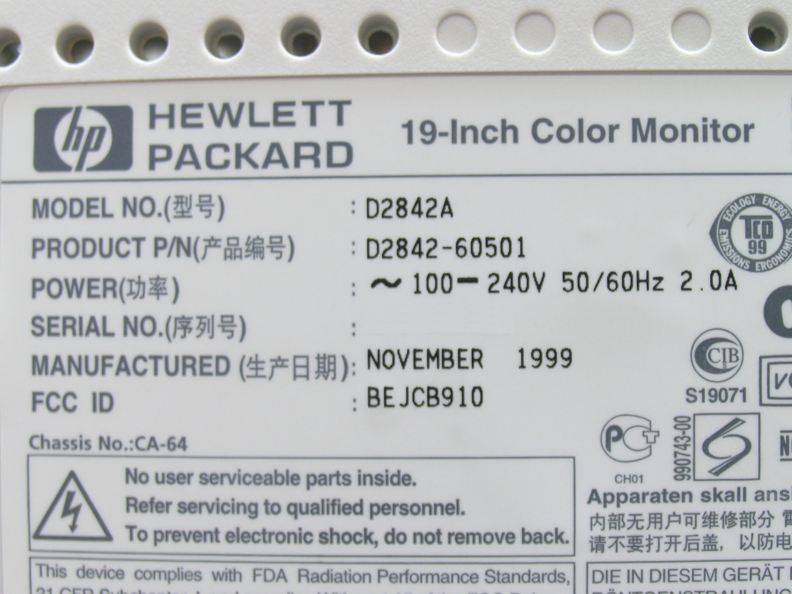
Some electrical devices will show a current rating (shown in amps, or A) and not a VA rating or W rating. Usually, this current rating is a maximum expected current. Maximum current usually occurs at the lowest input voltage, so calculate the VA by multiplying the current rating (A) times the lowest voltage shown on the device. Then, assume the device consumes an equal number of W as mentioned in the previous paragraph. For example, the picture below shows an input voltage range of 100 to 240 V and 2 A (all are AC). The VA would be the current, 2 A, times the lowest voltage, 100, which yields 200 VA. You could then assume this device consumes 200 W.

Monday, January 23, 2012

Six of seven new Agilent power supplies are autorangers, but what is an autoranger, anyway?

In this blog, I avoid writing posts that are heavily product focused since my intention is generally to provide education and interesting information about power products instead of simply promoting our products. However, when we (Agilent) come out with new power products, I think it is appropriate for me to announce them here. So I will tell you about the latest products announced last week, but I also can’t resist writing about some technical aspect related to these products, so I chose to write about autorangers. But first…..a word from our sponsor….

From last week’s press release, Agilent Technologies “introduced seven high-power modules for its popular N6700 modular power system. The new modules expand the ability of test-system integrators and R&D engineers to deliver multiple channels of high power (up to 500 watts) to devices under test.” Here is a link to the entire press release:

http://www.agilent.com/about/newsroom/presrel/2012/17jan-em12002.html

I honestly think these new power modules are really great additions to the family of N6700 power products we continue to build upon. We have several mainframes in which these power modules can be installed and now offer 34 different power modules that address applications in R&D and in integrated test systems. Oooooppps, I slipped into product promotion mode there for just a short time, but it was because I really believe in this family of products….I hope you will forgive me!

OK, now on to the more fun stuff! Since six of these seven new power modules are autorangers, let’s explore what an autoranger is. Agilent has been designing and selling autorangers since the 1970s (we were Hewlett-Packard back then) starting with the HP 6002A. To understand what an autoranger is, it will be useful to start with an understanding of what a power supply output characteristic is.

Power supply output characteristic
A power supply output characteristic shows the borders of an area containing all valid voltage and current combinations for that particular output. Any voltage-current combination that is inside the output characteristic is a valid operating point for that power supply.

There are three main types of power supply output characteristics: rectangular, multiple-range, and autoranging. The rectangular output characteristic is the most common.

Rectangular output characteristic
When shown on a voltage-current graph, it should be no surprise that a rectangular output characteristic is shaped like a rectangle. See Figure 1. Maximum power is produced at a single point coincident with the maximum voltage and maximum current values. For example, a 20 V, 5 A, 100 W power supply has a rectangular output characteristic. The voltage can be set to any value from 0 to 20 V, and the current can be set to any value from 0 to 5 A. Since 20 V x 5 A = 100 W, there is a singular maximum power point that occurs at the maximum voltage and current settings.

Multiple-range output characteristic
When shown on a voltage-current graph, a multiple-range output characteristic looks like several overlapping rectangular output characteristics. Consequently, its maximum power point occurs at multiple voltage-current combinations. Figure 2 shows an example of a multiple-range output characteristic with two ranges also known as a dual-range output characteristic. A power supply with this type of output characteristic has extended output range capabilities when compared to a power supply with a rectangular output characteristic; it can cover more voltage-current combinations without the additional expense, size, and weight of a power supply of higher power. So, even though you can set voltages up to Vmax and currents up to Imax, the combination Vmax/Imax is not a valid operating point. That point is beyond the power capability of the power supply and it is outside the operating characteristic.

Autoranging output characteristic
When shown on a voltage-current graph, an autoranging output characteristic looks like an infinite number of overlapping rectangular output characteristics. A constant power curve (V = P / I = K / I, a hyperbola) connects Pmax occurring at (I1, Vmax) with Pmax occurring at (Imax, V1). See Figure 3.

An autoranger is a power supply that has an autoranging output characteristic. While an autoranger can produce voltage Vmax and current Imax, it cannot produce them at the same time. For example, one of the new power supplies just released by Agilent is the N6755A with maximum ratings of 20 V, 50 A, 500 W. You can tell it does not have a rectangular output characteristic since Vmax x Imax (= 1000 W) is not equal to Pmax (500 W). So you can’t get 20 V and 50 A out at the same time. You can’t tell just from the ratings if the output characteristic is multiple-range or autoranging, but a quick look at the documentation reveals that the N6755A is an autoranger. Figure 4 shows its output characteristic.

Autoranger application advantages
For applications that require a large range of output voltages and currents without a corresponding increase in power, an autoranger is a great choice. Here are some example applications where using an autorangers provides an advantage:
• The device under test (DUT) requires a wide range of input voltages and currents, all at roughly the same power level. For example, at maximum power out, a DC/DC converter with a nominal input voltage of 24 V consumes a relatively constant power even though its input voltage can vary from 14 V to 40 V. During testing, this wide range of input voltages creates a correspondingly wide range of input currents even though the power is not changing much.
• There are a variety of different DUTs of similar power consumption, but different voltage and current requirements. Again, different DC/DC converters in the same power family can have nominal input voltages of 12 V, 24 V, or 48 V, resulting in input voltages as low as 9 V (requires a large current), and as high as 72 V (requires a small current). The large voltage and current are both needed, but not at the same time.
• A known change is coming for the DC input requirements without a corresponding change in input power. For example, the input voltage on automotive accessories could be changing from 12 V nominal to 42 V nominal, but the input power requirements will not necessarily change.
• Extra margin on input voltage and current is needed, especially if future test changes are anticipated, but the details are not presently known.

Monday, January 9, 2012

When powering multiple DUTs, should I use multiple small power supplies or one big power supply?

If you have to provide DC power to multiple devices under test (DUTs) at the same time, you will have to choose between using multiple smaller power supplies to provide power to each individual DUT (Figure 1) or one big power supply to power all of the DUTs at once (Figure 2). As will most choices, each has advantages and disadvantages. However, in this case, the advantages of choosing multiple smaller power supplies seem to outnumber those for the single bigger supply.


One of my colleagues, Bob Zollo, wrote an article on this topic that appeared in Electronic Design on October 12, 2011. Here is a link to the article:

http://electronicdesign.com/test-amp-measurement/powering-multiple-duts-parallel-consider-individual-supplies

Below is my summary of the contents:

Advantages of choosing multiple smaller power supplies
• Enables individual DUT current measurements without additional hardware
• Enables individual DUT voltage control
• Enables individual DUT shutdown upon DUT failure
• Enables individual DUT galvanic disconnect with relays inside power supply
• Prevents one DUT inrush current from disturbing other DUT’s voltage
• Prevents one DUT failure from affecting other DUT testing
• Isolates power supply failure to one DUT instead of affecting all DUTs

Advantages of choosing one big power supply
• Power supply hardware is less expensive
• Less power supply hardware to calibrate

The disadvantages of the smaller power supply choice are that the total power supply hardware is more expensive and is a larger quantity of hardware to calibrate. The disadvantages of the one big power supply are that it does not provide any of the advantages listed for the smaller supplies.

So you can see that the multiple smaller power supply choice has more advantages over the one big power supply choice. For the one big power supply choice, current monitoring and relays can be added in series with each DUT; however, this will contribute significantly to the cost of the system. If your application does not require you to monitor or control the power to each of your DUTs individually, you may be able to use the less capable one big power supply approach. Otherwise, use multiple smaller power supplies to get all of the performance, measurement, and control you need to test your DUTs.

Tuesday, December 6, 2011

Should I Use a Switching or Linear DC Power Supply For My Next Test System? (part 4 of 4)

Part 4 of 4: Making the Comparison and Choice
In the first three parts of this post we looked at the topologies and merits of linear DC power supplies, traditional and high-performance switching DC power supplies, and common mode noise current considerations of each. So now in this final part we have reached a point where we can hopefully make an informed comparison and choice. Tables 1 and 2 summarize several key qualitative and quantitative aspects of all three DC power supply types, based on what we have learned.
Table 1: Qualitative comparison of DC power supply topologies

Table 2: Quantitative comparison of DC power supply topologies

So what DC power supply topology is the best choice for your next test system? In the past it usually ended up having to be a linear topology to meet performance requirements in most all but very high power, lower performance test situations. However, high-performance switching DC power supplies have nowadays for the most part closed the performance gap with linear DC power supplies. And, at higher power, the favorable choice may come down to selecting between several different switching DC power supplies only, due to their cost, size, and availability. So the answer is you need to make a choice based on how well the power supply meets your performance, space, and cost requirements, rather than basing the choice on its topology. Except for the most demanding low power test applications, like those needing the performance of a source measure unit (SMU), chances are much higher these days that the next DC power supply you select for your next test system you will be a switcher (and you possibly may not even realize it). What has been your experience?

Tuesday, November 29, 2011

Should I Use a Switching or Linear DC Power Supply For My Next Test System? (part 3 of 4)

Part 3 of 4: DC Power Supply Common Mode Noise Current Considerations
Common mode noise current is a fact of life that manifests itself in many ways in test systems. There are several mechanisms that couple unwanted common mode noise currents into ground loops. An excellent overview on this is given in a two part post on the General Purpose Test Equipment (GPETE) blog “Ground Loops and Other Spurious Coupling Mechanisms and How to Prevent Them” (click here). However this is also an important consideration with our choice of a DC system power supply for testing as they are a source of common mode noise current. This is one area where linear DC power supplies still outperform switching DC power supplies. This can become a concern in some highly noise-sensitive test applications. As shown in Figure 1 the common mode noise current ICM is a noise signal that flows out of both output leads and returns through earth. By nature it is considered to be a current signal due to its relatively high associated impedance, ZCM.

Figure 1: Common Mode Noise Current and Path

Common mode noise current is often much greater in traditional switching DC power supplies. High voltage slewing (dv/dt) of the switching transistors capacitively couples through to the output, in extreme cases generating up to hundreds of milliamps pk-pk of high frequency current. In comparison, properly designed linear DC power supplies usually generate only microamps pk-pk of common mode noise current. It is worth noting even a linear DC power supply is still capable of generating several milliamps pk-pk of common mode noise current, if not properly designed. High-performance switching DC power supplies are much closer to the performance of a linear. They are designed to have low common mode noise current, typically just a few milliamps.

Common mode noise current can become a problem when it shows up as high frequency voltage spikes superimposed on the DC output voltage. This depends on the magnitude of current and imbalance in impedances in the path to the DUT. If large enough, this can become more troublesome than the differential mode noise voltage present. Generally, the microamp level of a linear DC power supply is negligible, while hundreds of milliamps from a traditional switching DC power supply may be cause for concern. Because common mode noise current is often misunderstood or overlooked, one may be left with a false impression that all switching DC power supplies are simply unsuitable for test, based on a bad experience with using one, not being aware that its high common mode noise current was actually the underlying cause.

In practice, at typical levels, common mode noise current often turns out not to be an issue. First, many applications are relatively insensitive to this noise. For example, equipment in telecommunications and digital information systems are powered by traditional switching DC power supplies in actual use and are reasonable immune to it. Second, where common mode noise current is more critical, the much lower levels from today’s high-performance switching DC power supplies makes it a non-issue in all but the most noise sensitive applications.

In those cases where common mode noise current proves to be a problem, as with some extremely sensitive analog circuitry, adding filtering can be a good solution. You can then take advantage of the benefits a switching DC power supply has to offer. A high-performance switching DC power supply having reasonably low common mode current can usually be made to work without much effort in extremely noise-sensitive applications, using appropriate filtering, capable of attenuating the high frequency content present in the common mode noise current. Such filtering can also prove effective on other high frequency noises, including AC line EMI and ground loop pickup. These other noises may be present regardless of the power supply topology.

Coming up next is the fourth and final part where we make our overall comparison and come to a conclusion on which power supply topology is best suited for test.

References:
1. Taking The Mystery Out Of Switching-Power-Supply Noise Understanding the source of unspecified noise currents and how to measure them can save your sanity
By Craig Maier, Hewlett Packard Co. © 1991 Penton Publishing, Inc.

Wednesday, November 23, 2011

Should I Use a Switching or Linear DC Power Supply For My Next Test System? (part 2 of 4)

Part 2 of 4: Switching DC system power supply attributes
In part 1 we looked at the topology and merits of a linear DC power supply. To be fair we now have to give equal time to discuss the topology and merits of a switching DC system power supply, to make a more informed choice of what will better suit our needs for powering up and testing our devices.

Traditional switching DC power supply topology
The basic traditional switching power supply depicted in Figure 2 is a bit more complex compared to a linear power supply:
1. The AC line voltage is rectified and then filtered to provide an unregulated high voltage DC rail to power the following DC-to-DC inverter circuit.
2. Power transistors switching at 10’s to 100’s of kHz impose a high voltage, high frequency AC pulse waveform on the transformer primary (input).
3. The AC pulse voltage is scaled by the transformer turns ratio to a value consistent with the required DC output voltage.
4. This transformer secondary (output) AC voltage is rectified into a pulsed DC voltage.
5. An LC (inductor-capacitor) output filter averages the pulsed voltage into a continuous DC voltage at the power supply’s output.
6. As with a linear power supply, an error amplifier compares the DC output voltage against a reference to regulate the output at the desired setting.
7. A modulator circuit converts the error amplifier signal into a high frequency, pulse width modulated waveform to drive the switching power transistors.


Figure 2: Basic switching DC power supply circuit

In spite of being more complex the key thing is its much higher operating frequency, several orders of magnitude over that of a linear power supply, greatly reduces the size of the magnetic and filtering components. As a result traditional switching DC power supplies have some inherent advantages:
• High power conversion efficiency of typically 85%, relatively independent of output voltage setting.
• Small size and lightweight, especially at higher power.
• Cost effective, especially at higher power.

Traditional switching DC power supplies also have some typical disadvantages:
• High output noise and ripple voltage
• High common mode noise current
• Slow transient response to AC line and DC output load changes.


High-performance switching DC power supplies lessen the gap
Traditional switching DC power supply performance is largely a result of optimizing well established switching topologies for cost, efficiency and size, exactly the areas where linear DC power supplies suffer. Performance generally had been a secondary consideration for switching DC power supplies. However, things have now improved to better address the high-performance needs for electronics testing. Incorporating more advanced switching topologies, careful design, and better filtering, high-performance switching DC power supplies compare favorably with linear DC power supplies on most aspects, while still retaining most of the advantages of switchers.

So our choice on whether to use a linear or switching power supply has now gotten a bit more difficult! One area that still differentiates these DC power supply topologies is common mode current noise, worthy of its own discussion, which is exactly what I will do in part 3, coming up next!

Tuesday, November 15, 2011

Should I Use a Switching or Linear DC Power Supply For My Next Test System? (part 1 of 4)

Part 1 of 4: Linear System DC Power Supply Attributes
To kick things off I thought it would be helpful to start with a short series of posts discussing something fundamental we’re often faced with; that is making the choice of whether to use a switching or linear DC power supply to power up our devices under test. In part 1 here I’ll begin my discussion with the topology and merits of linear DC power supplies, as I have heard countless times from others that only a linear power supply will do for their testing, principally due to its low output noise. Of course we do not want to take the chance of having power supply noise affect our devices’ test results. While I agree a linear DC power supply is bound to have very low noise, a well-designed switching DC power supply can have surprisingly good performance. So the choice may not be as simple anymore. The good thing here however is this may give us a lot more to choose from, something that may better meet our overall needs, including size and cost, among other things.

Linear DC Power Supply Topology
A linear DC power supply as depicted in Figure 1 is relatively simple in concept and in basic implementation:
  1. A transformer scales the AC line voltage to a value consistent with the required maximum DC output voltage level.
  2. The AC voltage is then rectified into DC voltage.
  3. Large electrolytic capacitors filter much of the AC ripple voltage superimposed on the unregulated DC voltage.
  4. Series-pass power transistors control the difference between the unregulated DC rail voltage and the regulated DC output voltage. There always needs to be some voltage across the series pass transistors for proper regulation.
  5. An error amplifier compares the output voltage to a reference voltage to regulate the output at the desired setting.
  6. Finally, an output filter capacitor further reduces AC output noise and ripple, and lowers output impedance, for a more ideal voltage source characteristic.

Figure 1: Basic Linear DC Power Supply Topology

Linear DC power supply design is well established with only incremental gains now being made in efficiency and thermal management, for the most part. Its straightforward configuration, properly implemented, has some inherent advantages:

  • Fast output transient response to AC line and output load changes
  • Low output noise and ripple voltage, and primarily having low frequency spectral content
  • Very low common mode noise current
  • Cost competitive at lower output power levels (under about 500 watts)

It also has a few inherent disadvantages:

  • Low power efficiency, typically no better than 60% at full output voltage and decreases with lower output voltage settings
  • Relatively large physical size and weight
  • High cost at higher power (above about 500 watts)

So it sounds like a linear power supply has to be the hands-down winner especially for low power applications. Or not? To make a more-informed choice we need to look at the topology and merits of a switching power supply, which I will be doing in part 2!