Friday, June 29, 2012

Using Power Supply Status Registers in your Program – Not So Scary


Hello everyone!  Today I am going to talk about how to use the Operation Status and Questionable Status Registers on Agilent’s power supplies.  All of Agilent’s SCPI based power supplies use these registers.  Figure 1 is a pictorial representation of the status system of the Agilent N6700 Modular Power System:

Figure 1 N6700 Status Model
 
Looks pretty daunting, doesn’t it?  After reading this blog post, it won’t be so scary anymore.   There are many great uses for these registers in your programs.

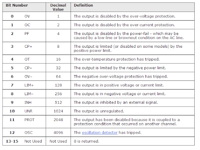
The Questionable Status Group lets you know if your power supply is in an abnormal operating state.  Sometimes your power supply will be in protect mode when these states are encountered.  You typically want to query this to make sure that your power supply does not transition to one of these abnormal states.  Here is a list of all the members of the Questionable Status Group:

Figure 2 N6700 Questionable Status Group


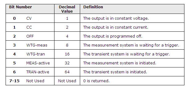
The Operation Status Group provides the normal operating modes of the power supply.  You typically want to query this register to either make sure that the power supply is either in the correct operating state or that it has completed some task (such as initiating a trigger or performing a measurement).  Here are the different members of the Operation Status Group:

 Figure 3 Operation Status Group


There are multiple ways to program using the registers.  The main way that I query the resisters is using the Condition Register.  The Condition Register will give you the real time status of the register.  Reading this register does not clear it.   A good example of using this is when you are initiating a triggered measurement:

 
INIT:ACQ (@1)                                    //This initiates the Acquire trigger system
Do
STAT:OPER:COND? (@1)       //Check the status register
               status = read
Loop Until (status And 8) = 8

*TRG  


Looking at Fig 3, 8 is the WTG_MEAS bit.  Once this is true, the unit is ready to be triggered.  This lets you make sure that you are not triggering the unit before the initiation is done.  Note that all of the statuses are referred to by the instrument by their by the bit weight (listed in the tables as the decimal value).  When you are looking for multiple statues, you need to add the bit weights.

 
The other main method of Querying the registers is using the Event register.  The Event Register is different than the Condition Register in that it keeps track of transitions in the statuses.  It does not matter when the status change happened, the Event Register will catch it and keep it until it is read back.   You do need to tell the power supply which statuses you are concerned with using the Negative Transition (STAT:OPER:NTR) and the Positive Transition (STAT:OPER:PTR) commands.  The Event Register is a latching register that will clear after it is read.  An example of using this register is when you want to make sure that there were no momentary transitions into an unwanted status.  In the following example, you want to make sure that your power supply does not go into the Unregulated mode (UNR) before you make a current measurement:

STAT:QUES:PTR 1024,(@1)            // This is the UNR bit
STAT:QUES:NTR 0, (@1)                // We are only interested in a positive transition
Body of  your program
STAT:QUES:EVEN?                        //Query the register
Status = readback
If status And 1024 =1024 then
 exit                                     //If the unit went UNR, exit
Else
                MEAS:CURR? (@1)      //measure current
                Curr=readback
End if

 
In this case, UNR is bit weight 1024.  When the unit transitions to the unregulated state (the bit transitions from 0 to 1), this bit gets set. 


As you can tell by Figure 1, there is a bunch more that you can do using status, including Service Requests but I will save those for a possible future blog post.


Please feel free to post any questions or comments here.


Thursday, June 28, 2012

Some Basics on Battery Ratings and Their Validation


A key aspect of optimizing battery run-time on battery powered mobile devices is measuring and analyzing their current drain to gain greater insight on how the device is making use of its battery power and then how to make better use of it. I went into a bit of detail on this in a previous posting, “Using Current Drain Measurements to Optimize Battery Run-time of Mobile Devices”.

A second aspect of optimizing battery run-time is making certain you are making optimum use of the battery powering the device. This starts with understanding and validating the battery’s stated capacity and energy ratings. Simply assuming the battery meets or exceeds its stated ratings without validating them is bound to leave you coming up shorter than expected on run-time.  It is critical that you validate them per the manufacturer’s recommended conditions. This serves as a starting point of finding out what you can ultimately expect from the battery you intend to use in your device. More than likely constraints imposed by the nature of your device and its operating conditions and requirements will further reduce the amount of capacity you can expect from the battery in actual use.

A battery’s capacity rating is the total amount of charge the battery can deliver. It is product of the current it can deliver over time, stated as ampere-hours (Ah) or miiliampere-hours (mAh). Alternately the charge rating is also stated as coulombs (C), where:
·         1 coulomb (C)= 1 ampere-sec
·         1 ampere-hour (Ah)= 3,600 coulombs

A battery’s energy rating is the total amount of energy the battery can deliver. It is the product of the power it can deliver over time, stated as watt-hours (Wh) or milliwatt-hours (mWh). It is also the product of the battery’s capacity (Ah) and voltage (V). Alternately the energy rating is also stated as joules (J) where:
·         1 joule (J)= 1 watt-second
·         1 watt-hour (Wh) = 3,600 joules

One more fundamental parameter relating to a battery’s capacity and energy ratings is the C rate or charge (or discharge) rate. This is the ratio of the level of current being furnished (or drawn from, when discharging) the battery, to the battery’s capacity, where:
·         C rate (C) = current (A) / (capacity (Ah)
·         C rate (C) = 1 / charge or discharge time

It is interesting to note while “C” is used to designate units of C rate, the units are actually 1/h or h-1. The type of battery and its design has a large impact on the battery’s C rate. Batteries for power tools have a high C rate capability of 10C or greater, for example, as they need to deliver high levels of power over short periods of time. More often however is that many batteries used in portable wireless mobile devices need to run for considerably longer and they utilize batteries having relatively low C rates. A battery’s capacity is validated with a C rate considerably lower than it is capable of as when the C rate is increased the capacity drops due to losses within the battery itself.

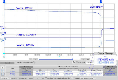
Validating a battery’s capacity and energy ratings requires logging the battery’s voltage and current over an extended period of time, most often with a regulated constant current load. An example of this for a lithium ion cell is shown in Figure 1 below. Capacity was found to be 12% lower than its rating.

Figure 1: Measuring a battery’s capacity and energy

Additional details on this can be found in a technical overview I wrote, titled “Simply Validating a Battery’s Capacity and Energy Ratings”. As always, proper safety precautions always be observed when working with batteries and cells. Validating the battery’s stated capacity and energy ratings is the first step. As the battery is impacted by the device it is powering, it must then be validated under its end-use conditions as well. Stay tuned!