Friday, November 30, 2012

Voltage Noise and You

One of the most important specifications for many of our customers on our power supplies is voltage noise.  We specify both peak to peak voltage noise and RMS voltage noise for frequencies ranging from 20 Hz to 20 MHz.  Agilent sells precision power supplies and you need to have low voltage noise in order to be a precision power supply and to make precision measurements. 


I sat down with some engineers today before sitting down to type up my blog post.  I wanted to find out some of the main causes for voltage noise in our supplies so that I can share it with you Watt's Up readers.  Please note that each of these reasons could be a blog post of its own but for brevity's sake I am going to come at this for a high level.  Since our newest supplies have the high power density, they are mostly switch mode power supplies.   The top cause of noise in switch mode power supplies is the frequency of the switching inverters.  This is inherent to the design of the supply.  The second most common cause of noise is common mode current noise that turns into normal mode voltage noise.  We have filtering and common mode chokes inside the supplies but some still gets through and comes out the output as normal mode voltage.  The third most likely cause is noise from operational amplifiers that makes its way to the outputs.  After talking to our designer I came out with a new respect for the challenges they face when having to deal with this!
 

I recently did a video on how to make this measurement:


I wanted to use the Watt’s Up blog to add some more information.

The general schematic for noise testing is:
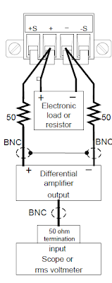
One thing that I wanted to do in the video but was not able to for brevity’s sake was talk about the differential amplifier.  The differential amplifier is important for two key reasons.  The first reason is that the differential amplifier will greatly reduce the common mode noise on the output.  This is important because you want to measure the noise between the outputs.  The other benefit of the differential amplifier is that it multiplies the output by 10.  This multiplication enables us to use more accurate ranges in both the scope and the RMS voltmeter which is very important when you want to keep the measurement uncertainties of your measurements down.


When you do the noise test, typically you do it at the full power point.  To get the full current, you can either use an electronic load or a fixed resistor.  Typically on a lower noise supply (such as the N6761A) you want to use a fixed resistor since the electronic load will introduce its own noise to the measurement.  This is not really an issue for power supplies with higher noise because their output noise is higher than the noise from the load.  In all honesty, it also tends to be difficult to find 500 W resistors so the load is a great help in those instances too!


The last measurement item that I want to talk about is the scope setup.  The scope should be AC coupled and have the filter turned on (since we only specify noise to 20 MHz, we want to filter anything above this out). We recommend that you put the scope in peak detect mode and turn the statistics so that you can see the highest and the lowest voltages recorded.    This will give you the true variation in the power supply output.  Your peak to peak voltage noise will be this difference divided by the gain of the diff amp.  After taking the peak to peak measurement, I typically move the connector over to the RMS voltmeter to take that measurement.  There are no special settings for the RMS voltmeter, you just need to remember to divide by the gain of the differential amplifier.

That is a really quick overview of voltage noise.  Please feel free to leave any questions in the comments section of this blog.   


Wednesday, November 21, 2012

How can I get more power from my power supplies?

If you need more voltage than one of your power supply outputs can provide, you can put power supply outputs in series to increase the total voltage. If you need more current than one of your power supply outputs can provide, you can put power supply outputs in parallel to increase the total current. However, you do have to take some precautions with series or parallel configurations.

Precautions for series connections for higher voltage:
  • Never exceed the floating voltage rating (output terminal isolation) of any of the outputs
  • Never subject any of the power supply outputs to a reverse voltage
  • Connect in series only outputs that have identical voltage and current ratings
Precautions for parallel connections for higher current:
  •  In most applications, one output must operate in constant voltage (CV) mode and the other(s) in constant current (CC) mode
  •  In most applications, the load on the output must draw enough current to keep the CC output(s) in CC mode
  • Connect in parallel only outputs that have identical voltage and current ratings

You can use remote sensing with either a series or parallel configuration. Figure 1 shows remote sensing for series outputs and Figure 2 shows remote sensing for parallel outputs.


You can find more information about power supply series and parallel configurations in an Agilent document called “Ten Fundamentals You Need to Know About Your DC Power Supply” by clicking on this link:
Refer to tip number 4 on page 6. This document also covers nine other useful power supply fundamentals.

Thursday, November 15, 2012

Validating battery capacity under end-use conditions for battery powered mobile devices


One aspect (of many) I have talked about for optimizing battery life for battery powered mobile devices is assessing the battery’s actual capacity. Not only do you need to assess its capacity under conditions as stated by the manufacturer but also under conditions reflecting actual end use.

Validating the battery under a manufacturer’s stated conditions establish a starting point of what you might be achievable in how much capacity you can obtain from the battery and if it is in line with what the manufacturer states. Sometime it can be less for a variety of reasons. Even subtle differences in stated conditions can lead to fairly substantial differences in capacity. The stated conditions usually provide a “best case” achievable value for capacity. Do not be surprised if your results for the battery’s capacity fall a little short of the best case value provided by the manufacturer. With a little work you may be able to determine what subtle difference caused it, or simply, the best case value given is a bit optimistic.

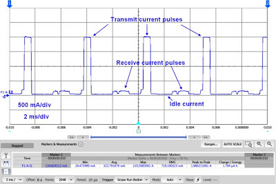
Validating the battery under end-use conditions helps establish the difference you can expect between the battery’s capacity for rather ideal stated conditions against end-use conditions. Battery powered mobile devices draw current in a pulsed fashion, with high peaks in relation to the overall average current drain. An example of this kind of dynamic current drain is shown in Figure 1. In this case it is the active mode current drain of a GPRS smart mobile phone.


Figure 1: GPRS smart mobile phone dynamic current drain waveform

This usually significantly degrades the battery’s delivered capacity in comparison to the manufacturer’s stated conditions, which are based on a constant DC current discharge. If you do not take the impact of end-use loading conditions on the battery’s capacity into account there is a good chance the mobile device’s run-time will fall quite a bit short of expectations.

The usual way to validate a battery’s capacity under end-use conditions is to actually hook the battery together with its device, connect up logging instrumentation for recording the battery run down voltage and current over time, and then placing the device in a desired operating mode and let it run until the battery is run down. While a battery run-down test like this is useful to do it has a couple of issues when trying to focus explicitly on just the battery:
  • It is a test of the combination of the battery together with its host device. The host device also has influence on the test’s outcome and must be taken into account in assessing just the battery under end-use.
  • It can often be complex and difficult to set up the device in its desired operating condition, requiring a substantial amount of supporting equipment to recreate its environment for providing a realistic operating condition.
  • It can sometimes be difficult to get consistently repeatable results with the actual device.

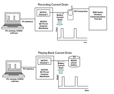
An alternative to repeatedly using the actual device is to use an electronic load that can draw a dynamic current representative of the actual device the electronic load is being used in place of. In some cases a simple low duty cycle, high crest factor pulsed current waveform can be directly programmed into the electronic load. In cases where the host device’s current drain waveform is a bit more complex it may be useful to have an electronic load that is able to “play back” a digitized waveform file that is a representative portion of the device’s actual current drain, on an ongoing basis to run down the battery. As one example we put features into our 14585A software to simplify this record and playback approach using our N6781A 2-quadrant DC source measure module. This set up is depicted in Figure 2.


Figure 2: Current drain record and playback set up using the 14585 and N6781A

In the first half of this process the N6781A serves as a voltage source to power up the device while digitizing its dynamic current drain waveform. In the second half of this process the captured current drain waveform is inverted and then played back by the N6781A now instead operating as a constant current load connected to a battery to discharge it. A colleague in our office recently completed a video of how to do this record and playback process using a digital camera as an example, capturing the current drain waveform of the process of taking a picture. This could be played back repeatedly to determine how many pictures could be taken with a set of batteries, for example. I know with my digital camera I need to take a spare set of batteries with me as it uses up batteries quite quickly! The video is available to be viewed at the following link:“record and playback video”

Thursday, November 8, 2012

Configuring an Electronic Load for Zero Volt Operation


DC electronic loads are indispensable for testing a variety of DC power sources. There are a number of situations that call for testing DC power sources at low voltage, even right down to zero volts. Often this is also at relatively high current of many tens of amps or greater. Some examples include:
  • Low output voltage power supplies and DC/DC converters (mostly for digital circuit power)
  • Solar cell I-V testing, down to zero volts
  • Fuel cell testing
  • Single cell battery testing
  • Power supply true output short-circuit testing, down to zero volts


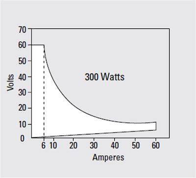
It becomes challenging for the test engineer to find adequate DC electronic loads for low voltage operation, especially at high currents. Many DC electronic loads, including the ones Agilent Technologies provides, use multiple power FETs for their input loading element. While a power FET can actually operate down to zero volts, this is at zero current as well. At high current a few volts is typically needed for stable, dynamic operation at full current.  As one example Figure 1 depicts the input I-V characteristics of an Agilent N3304A DC electronic load.


Figure 1: Agilent N3304A DC electronic load input I-V characteristics

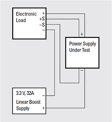
An effective solution for low voltage electronic load operation, right down to zero volts, for the electronic load’s full rated current, is to connect a low voltage boost power supply in series with the electronic load’s input. An example of this set up is depicted in Figure 2.


Figure 2: Zero volt DC electronic load set up

The electronic load now sees the sum of the boost supply’s and DUT’s voltages. Selecting a boost supply having adequate voltage will assure the electronic load will be able to operate at full performance at full current, even when the voltage at the DUT is zero. There are a few things that need to be paid attention to:
  • The electronic load needs to dissipate the total power of both the boost supply and DUT
  • The DUT needs to be adequately safeguarded against reverse polarity if the electronic load is inadvertently turned on too hard
  • The electronic load’s voltage sensing must be able to accommodate the extra voltage difference between the electronic load and DUT, due to the boost supply voltage
  • The boost supply ripple and noise (PARD) can contribute to noise measurements made on the DUT


Due to these considerations not all electronic loads may be well suited for zero volt operation with a boost supply so it is necessary to validate if a particular electronic load under consideration can be applied in this manner first.  Further details about zero voltage load operation as well as using Agilent N3300 series DC electronic loads for this purpose are described in product note “Agilent Zero Volt Electronic Load”, publication number 5968-6360E. Click here to access