Hi everybody,
Last year, we introduced the Agilent N7900 Advanced Power System (hereon in shortened to N7900 APS). The N7900 APS is a full of great features that can only be accessed using the instrument's programming interface. The programming interface works very well but sometimes you just don't want write and troubleshoot a program, you just want something that works.
Well, I have the chance to share some pretty exciting news. We want to provide you software that makes some of these great features easy for you to use. The software is the 14585A Control and Analysis Software. This software was previously only available for the N6705 DC Power Analyzer.
The 14585A software is a standalone application that unlocks three key features: it allows you to look at a graphical representation of the measured data in Scope Mode, create arbitrary waveforms in Arb mode, and log long term data in datalogger mode. These three advanced features can be setup and run by adjusting a few settings and pressing a few buttons.
The software comes with a 30 day free trial so feel free to download it to check it out. Please note that you need at least version A.01.13 of the APS firmware in order to use the software.
You can find the latest APS firmware at:
APS Firmware
You can find the software at:
14585A Software
If you have any questions on the software, feel free to leave us some comments. Thanks for reading!

Wednesday, April 30, 2014
Tuesday, April 29, 2014
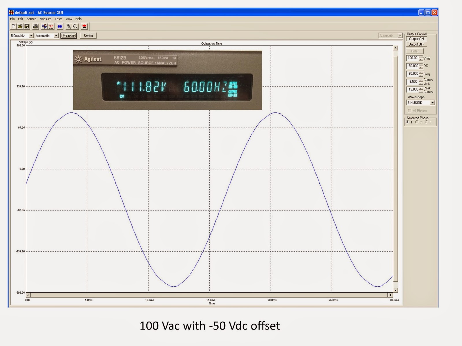
Measurement of AC plus DC voltage
One of our AC source customers recently asked me to justify the reading on the front panel of one of our AC sources set to produce a sine wave with a DC offset. He had our 6812B AC Power Source/Analyzer set to a sine wave of 100 Vac (60 Hz) and added a DC offset of 50 Vdc. These AC sources can produce output voltages of up to 300 Vrms and DC voltages up to +/- 425 Vdc. With his settings of 100 Vac and 50 Vdc, the front panel meter was reading 111.79 V with the meter set to measure AC+DC. At first this seemed like an odd result to me, but then I realized that we are simply measuring the rms (root-mean-square) of the total waveform (AC plus DC) and that should be the square-root of the sum-of-the-squares of the individual rms values. This can be mathematically proven fairly easily. Since the AC source Vac is set in rms volts and the rms of DC is simply the DC voltage:


This works even if the DC value is set to -50 Vdc instead of +50 Vdc since the value is squared. And sure enough, when I set the AC source output to 100 Vac and -50 Vdc, the front panel measurement shows 111.82 as expected. The small variation in the measured value compared to the exact calculated value is due to the slight inaccuracies in both the output setting and measurement system.

This works even if the DC value is set to -50 Vdc instead of +50 Vdc since the value is squared. And sure enough, when I set the AC source output to 100 Vac and -50 Vdc, the front panel measurement shows 111.82 as expected. The small variation in the measured value compared to the exact calculated value is due to the slight inaccuracies in both the output setting and measurement system.

So in summary, measurement of an rms waveform that consists of an AC signal plus a DC signal is the square-root of the sum-of-the-squares of the individual two values. It’s as simple as that!
Monday, April 28, 2014
Upcoming Seminar on Using Your Power Supply to Improve Test Throughput
I have provided here on “Watt’s up?” a number of ideas on
how you can improve your test throughput from time to time, as it relates on
how to make better use of you system power supplies to accomplish this. I have
categorized these ideas on how to improve throughput as either fundamental or
advanced.
In “How fundamental features of power supplies impact
your test throughput” (click here to review) I shared in a two-part posting
definitions of key fundamental power supply features that impact test
throughput and ways to make improvements to literally shave seconds off of your
test time.
One example (of several) of an advanced idea on improving
throughput I previously shared here is “Using the power supply status system to
improve test throughput” (click here to review). Here I explain how, by monitoring
the status system, you can improve throughput by not relying on using
excessively long fixed wait statements in your programming.
I hope you have found these ideas helpful. If you would
like to learn more about using your system power supply to improve your test
throughput I will be presenting a live web-based seminar this week, in just a
couple of days, April 30th, at 1:00 PM EST on this very topic!
In this seminar I will go through a number of things I’ve
shared here on “Watt’s up?” in the past, but in greater detail. In addition, I
have also prepared several new ideas as well in this seminar that you might
find of help for your particular test situation. You can register online at the following
(click here to access seminar description and registration). In case you miss the live event I expect you
will be able to register and listen to seminar afterward as well, as it will be
recorded.
So if improving your test throughput is important to you
I hope you are able to attend the seminar!
Thursday, April 3, 2014
Why have programmable series resistance on a power supply’s output?
A feature we’ve included on our 663xxA Mobile
Communications DC Sources, our N6781A 2-quadrant Source Measure Module, and
most recently our N69xxA and N79xxA Advanced Power System (APS) is the ability
to program in a value for a resistance that exists in series with the output
voltage. So why do we offer this?
Batteries are not
ideal voltage sources. They have a significant amount of equivalent series
resistance (ESR) on their output. Because of this, the battery’s output has a
voltage drop that is proportional to the current drawn by the DUT that is being
powered. An example of this is shown in the oscilloscope capture in Figure 1,
where a GPRS mobile handset is drawing pulsed transmit current from its
battery.
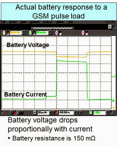
Figure 1: Battery voltage and current powering a GPRS
handset during transmit
In comparison, due to control feedback, a conventional DC
power supply has extremely low output impedance. At and near DC, for all
practical purposes, the DC output resistance is zero. At the same time, during
fast load current transition edges, many conventional DC power supplies can
have fairly slow transient voltage response, leading to significant transient
overshoots and undershoots with slow recovery during these transitions, as can
be seen in the oscilloscope capture in Figure 2.

Figure 2: Example general purpose bench power supply
powering a GPRS handset during transmit
It’s not hard to see that the general purpose bench power
supply voltage response is nothing close to that of the battery’s voltage
response and recognize that it will likely have a significant impact on the
performance of the GPRS handset. Just considering the performance of the
battery management, the battery voltage drop during loading and rise during
charging, due to the battery’s resistance, will impact discharge and charge
management performance.
We include programmable resistance in the above mentioned
DC power supplies as they are battery simulators. By being able to program a series output
resistance these power supplies are able to better simulate the voltage
response of a battery, as shown in Figure 3.
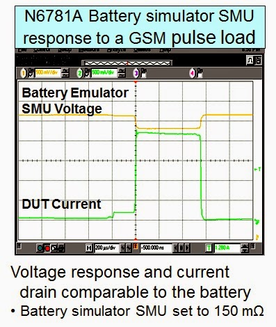
Figure 3: N6781A battery simulator DC source powering a
GPRS handset during transmit
While the 663xxA and N6781A are fairly low power meant to
simulate batteries for handheld mobile devices, The N69xxA and N79xxA APS units
are 1 and 2 KW power supplies meant to simulate much larger batteries used in
things like satellites, robotics, regenerative energy systems, and a number of
other higher power devices. Figure 4 shows the voltage response of an N7951A 1
KW APS unit programmed to 20 milliohms output impedance, having a +/- 10 amp
peak sine wave load current applied to its output.
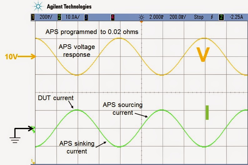
Figure 4: N7951A 1 KW APS DC source voltage response to
sine wave load
Monday, March 31, 2014
Use the FETCH Command to Minimize Your Measurement Time
Hi everyone,
There is another, very useful way to use the FETCH commands. I am not really sure what the best way to phrase it so I am going to take a shot and then illustrate with an example. When you send a measure command (say for voltage), the measurement system will also acquire the other measurement (in this case current) and you can send a FETCH command to retrieve that acquired data. Here is a very small example with some comments (all these commands tested on a N7952A Advanced Power System):
Example Snippet 1:
MEAS:VOLT? -> This will start a new acquisition and take the measurements
<read back the voltage measurement data>
FETC:CURR? -> This will return the current measured during the voltage measurement above
<read back fetched current measurements>
Since we have voltage and current measurements, the instrument can calculate power:
FETC:POW? -> P=V*I
<read back calculated power>
Please note that you can do this with arrays as well.
How can this save me time in my program you ask? Well these power supplies all have built in digitizers that you can access with some programming commands. The default measurement (at 60 Hz line frequency) is 3255 points measured at 5.12 us per point. That is a total measurement time of 16.67 ms. You have the ability to change this to fit your needs though. You can measure up to 512 Kpoints at up to 40,000 s per point. Every time you send a measure command you need to wait for the measurement to complete. For instance:
Example Snippet 2:
MEAS:VOLT?
<read back the voltage measurement data>
MEAS:CURR?
<read back the current measurement data>
You will need to wait for two acquisition periods because you are initiating two separate measurements. In the first example snippet, only the MEAS:VOLT? is initiating a measurement, the FETC:CURR is just reading data out of the instrument. The downside is that the data that you fetch is going to be of the same age as the last measurement you did so if you need something newer, you need to do a new measurement. Overall though I think that FETCH is a very useful command.
I hope people find this useful. Let us know if you have any questions by using the comments.
Friday, March 28, 2014
What is a floating power supply output?
First let me tell you that a floating power supply output is NOT what is shown below in Figure 1 (haha).
Now some background: earth ground is the voltage potential of the earth and to greatly reduce the risk of subjecting a person to an electrical shock, the outer covering (chassis) of most electrical devices is internally connected to a wire that is connected to earth ground usually through the power cord. The idea here is to ensure that all surfaces a person can touch are at the same voltage potential; namely, the one that he is standing on: earth ground. As long as that is true, the person can freely touch things without the risk of getting shocked due to two of the things he touches at the same time being at different voltage potentials, or one of the things being at a high voltage potential with respect to the earth. If the voltage difference is high enough, the person could be shocked. Earth grounding the chassis also protects the user if there is an internal problem with an electrical device causing its chassis to inadvertently come in contact with an internal high voltage wire. Since the chassis is earth grounded, an internal short to the chassis is really a short to ground and will blow a fuse or trip a circuit breaker to protect the user instead of putting the chassis at the high voltage. If you touched a chassis that had a high voltage with respect to ground on it, your body completes the path to ground and you get shocked!
So to protect the user (and for some other reasons), the chassis of Agilent power supplies are grounded internally through the ground wire (the third wire) in the AC input line cord. Additionally, most if not all of our Agilent power supplies have isolated (floating) outputs. That means that neither the positive output terminal nor the negative output terminal is connected to earth (chassis) ground. See Figure 2.

Figure 3 shows an example of non-floating outputs with the negative output terminal grounded.

For floating DC power supplies, the voltage potential appears from the positive output terminal to the negative output terminal. There is no voltage potential (at least, none with any power behind it) from either the positive terminal to earth ground or from the negative output terminal to earth ground. A power supply with a floating output is more flexible since, if desired, either the positive or negative terminal (or neither) can be connected to earth ground. Some devices under test (DUT) have a DC input with either the positive or negative input terminal connected to earth ground. If one of the power supply outputs was also internally connected to earth ground, when connected to the DUT, it could short out the power supply output. So power supplies with floating output terminals (no connections to earth ground) are more versatile.
If the outputs are floating from earth ground, we need to specify how far above or below earth ground you can float the output terminals. Our power supply documentation provides this information. For example, most Agilent power supply output terminals can float to +/-240 Vdc off of ground. You will frequently see the following in our documentation:

Also, some power supplies have different float ratings for the positive and negative output terminals. For example, for Agilent N5700 models rated for more than 60 Vdc, the following note in the manual means you can float the positive output terminal up to +/-600 Vdc from ground or the negative output terminal up to +/-400 Vdc from ground:

The output characteristic table may list this as “Output Terminal Isolation” as shown below which means the same thing as maximum float voltage:

Figure 4 shows an example of floating a power supply to 200 V above ground. The power supply output is set to 40 V.

You can see from the last example that you have to take the power supply output voltage into consideration when ensuring you are not violating the float voltage rating. If you exceed the float voltage rating of the power supply, you are potentially exceeding the voltage rating of internal parts that could cause the internal parts to fail or break down and present a shock hazard, so don’t violate the float voltage rating!
Monday, March 10, 2014
Upcoming software release unleashes the N7900 APS’s potential without any programming
Our N7900A Advanced Power System (APS) is well named,
being the most advanced power product we’ve introduced to date. In many ways it
is based on our N6700 series modular DC power system and N6705B DC power
analyzer, incorporating their capabilities, including:
- High precision programming and measurement
- Seamless measurement ranging
- High speed measurement digitization of voltage, current, and power
- Long term data logging of voltage, current, and power
- Output ARB and List capabilities
- And quite a bit more
In addition the N7900A APS brings quite a few new and
unique capabilities as well, including:
- Much greater output power
- Logic-configurable expression signal routing for advanced custom triggering and control
- Optional external dissipater unit for full two quadrant operation
- Optional black box recorder for post-test diagnostics when needed
- And quite a bit more
To take advantage of these advance capabilities does
require a bit of programming, which is to generally be expected for an
automated test environment, but in low volume design validation and R&D this
can slow down the desired quick time-to-result. The N6705B DC Power Analyzer,
in Figure 1, has a full-featured front panel menu and graphical display that
lets design validation and R&D users quickly configure and run complex
power-related tests on their devices. In comparison, the N6700 series, pictured
in Figure 2, does not have all the front panel capabilities of the N6705B and
can be looked on as the ATE version of this product platform, requiring
programming to take advantage of its advanced capabilities. The N6705B shares
all the same DC power modules that the N6700 series uses.
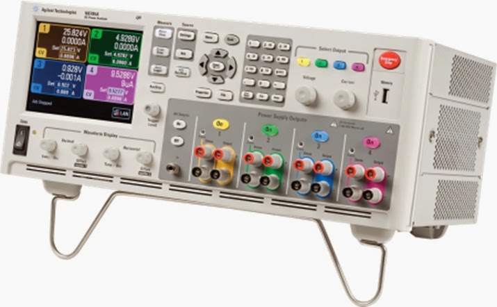
Figure 1: The N6705B DC Power Analyzer, primarily for
bench use
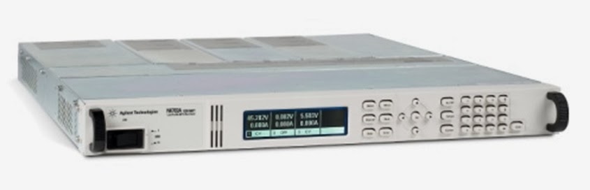
Figure 2: The N6700 series Modular DC Power System,
primarily for ATE
The N7900A APS is very similar in form and function to the
N6700 series, not having all the advanced front panel capabilities that the
N6705B has for bench-friendly use of its advanced features. I am really pleased
to be able to share with you that this is now changing! While we are not
creating a bench version of the N7900 APS, we are upgrading our 14585A Control
and Analysis software, which emulates the front panel of an N6705B and more, to
work with the N7900 APS as well. The 14585A will soon let you quickly and
easily create and configure complex power-related tests based on using the N7900
APS. I am fortunate enough to be working
with a beta version of the software. Some examples of things I was able to do
in just a few minutes were to capture the inrush current of an automotive
headlight, shown in Figure 3, and superimpose an AC sine wave disturbance on
top of the DC output, shown in Figure 4.

Figure 3: Auto headlamp inrush current captured with
14585A software and N7951A APS
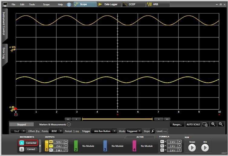
Figure 4: Sine wave voltage disturbance on top of DC generated
by 14585A software and N7951A APS
Subscribe to:
Posts (Atom)