Showing posts with label N6900. Show all posts

Friday, May 22, 2015

New performance options for the N6900A Advance Power System gives greater versatility for your test needs

Our N6900 and N7900 series Advanced Power System (APS) DC power supplies are some of our most sophisticated products, setting new levels of performance and capabilities on many fronts. They come in 1kW and 2kW power levels as shown in Figure 1 and can be grouped together to provide much greater power levels as needed.


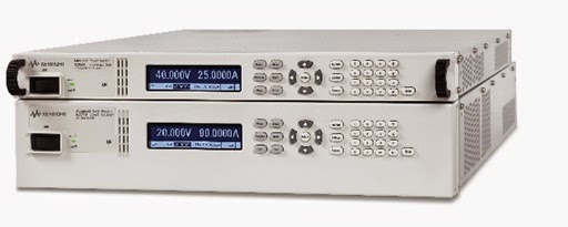
Figure 1: N6900 and N7900 Advanced Power System 1kW and 2kW models

Most noteworthy is that these can be turned into full two-quadrant DC sources by connecting up the optional 1kW N7909A Power Dissipator (2 needed for 2kW units) providing 100% power sinking capability. This makes APS an excellent solution for battery, battery management and many alternative energy applications, where both sourcing and sinking power are needed.
  • The N6900 series DC power supplies are designed for ATE applications where high test throughput and high performance is critical.
  • The N7900 series dynamic DC power supplies are designed for ATE applications where high speed dynamic sourcing and measurement is needed, in additions to high performance.

A lot more about these products is covered in another post on our General Purpose Electronic Test Equipment (GEPTE) blog when they were first announced. This is a great resource for learning more about APS and can be accessed from the following link: “New Advanced Power System: Designed to Overcome Your Toughest Test Challenges”

If you are a regular visitor to the “Watt’s Up?” blog no doubt you have seen we have shared a lot about how to do things with the N6900 series and N7900 series APS to address a number of difficult test challenges. A lot of times it would have otherwise required additional equipment or custom hardware to accomplish these tasks. While many of these examples are suitable for the N6900 and N7900, a good number of times examples make use of the additional capabilities only available in the N7900 series.

In certain test situations the N6900 series APS would be a great solution and lower cost than the N7900 series, if only it also had a certain additional capability. To this end Keysight has recently announced four new performance options for the N6900 series APS to address a specific test need you may have, as follows:
  1. Accuracy Package (option 301): Adds a second seamless measurement range for current
  2. Measurement Enhancements (Option 302): Adds external data logging and voltage and current digitizers with programmable sample rates
  3. Source and Speed Enhancements (Option 303): Adds constant dwell arbitrary waveforms and output list capability, and faster up and down programming speed
  4. Disconnect and Polarity-Reversal Relays (Option 760 and 761): Provides galvanic isolation and allows output voltage to be switched between positive and negative values

 Additional details about the N6900 series APS and the four new performance options are available from the recent press release, available at the following link: “Keysight Technologies adds Versatile Performance Options to Industry’s Fastest Power Supplies”

With these new options you now have a spectrum of choices in the Advanced Power System product family to better address any test challenges you may be faced with!

Friday, December 5, 2014

Why does the response time of OCP vary on the power supply I am using and what can I do about it? Part 2

In the first part of this posting (click here to review) I highlighted what kind of response time is important for effective over current protection of typical DUTs and what the actual response characteristic is for a typical over current protect (OCP) system in a test system DC power supply. For reference I am including the example of OCP response time from the first part again, shown in Figure 1.


Figure 1: Example OCP system response time vs. overdrive level

Here in Figure 1 the response time of the OCP system of a Keysight N7951A 20V, 50A power supply was characterized using the companion 14585A software. It compares response times of 6A and 12A loading when the current limit is set to 5A. Including the programmed OCP delay time of 5 milliseconds it was found that the actual total response time was 7 milliseconds for 12A loading and 113 milliseconds for 6A loading.  As can be seen, for reasons previously explained, the response time clearly depends on the amount of overdrive beyond the current limit setting.

As the time to cause over current damage depends on the amount of current in excess of what the DUT can tolerate, with greater current causing damage more quickly, the slower response at lower overloads is generally not an issue.  If however you are still looking how you might further improve on OCP response speed for more effective protection, there are some things that you can do.

The first thing that can be done is to avoid using a power supply that has a full output current rating that is far greater than what the DUT actually draws. In this way the overdrive from an overload will be a greater percentage of the full output current rating. This will normally cause the current limit circuit to respond more quickly.

A second thing that can be done is to evaluate different models of power supplies to determine how quickly their various current limit circuits and OCP systems respond in based on your desired needs for protecting your DUT. For various reasons different models of power supplies will have different response times. As previously discussed in my first part, the slow response at low levels of overdrive is determined by the response of the current limit circuit.

One more alternative that can provide exceptionally fast response time is to have an OCP system that operates independently of a current limit circuit, much like how an over voltage protect (OVP) system works. Here the output level is simply compared against the protect level and, once exceeded, the power supply output is shut down to provide near-instantaneous protection. The problem here is this is not available on virtually any DC power supplies and would normally require building custom hardware that senses the fault condition and locally disconnects the output of the power supply from the DUT. However, one instance where it is possible to provide this kind of near-instantaneous over current protection is through the programmable signal routing system (i.e. programmable trigger system) in the Keysight N6900A and N7900A Advanced Power System (APS) DC power supplies. Configuring this triggering is illustrated in Figure 2.


Figure 2: Configuring a fast-acting OCP for the N6900A/N7900A Advanced Power System

In Figure 2 the N7909A software utility was used to graphically configure and download a fast-acting OCP level trigger into an N7951A Advanced Power System. Although this trigger is software defined it runs locally within the N7951A’s firmware at hardware speeds. The N7909A SW utility also generates the SCPI command set which can be incorporated into a test program.


Figure 3: Example custom-configured OCP system response time vs. overdrive level

Figure 3 captures the performance of this custom-configured OCP system running within the N7951A. As the OCP threshold and overdrive levels are the same this can be directly compared to the performance shown in Figure 1, using the conventional, current limit based OCP within the N7951A. A 5 millisecond OCP delay was included, as before. However, unlike before, there is now virtually no extra delay due to a current limit control circuit as the custom-configured OCP system is totally independent of it. Also, unlike before, it can now be seen the same fast response is achieved regardless of having just a small amount or a large amount of overdrive.

Because OCP systems rely on being initiated from the current limit control circuit, the OCP response time also includes the current limit response time. For most all over current protection needs this is usually plenty adequate.  If a faster-responding OCP is called for minimizing the size of the power supply and evaluating the performance of the OCP is beneficial. However, an OCP that operates independently of the current limit will ultimately be far faster responding, such as that which can be achieved either with custom hardware or making use of a programmable signal routing and triggering system like that found in the Keysight N6900A and N7900A Advanced Power Systems.

Monday, June 23, 2014

Safeguarding your power-sensitive DUTs from an over power condition

Today’s system DC power supplies incorporate quite a variety of features to protect both the device under test (DUT) as well as the power supply itself from damage due to a fault condition or setting mishap. Over voltage protect (OVP) and over current protect (OCP) are two core protection features that are found on most all system DC power supplies to help protect against power-related damage.

OVP helps assure the DUT is protected against power-related damage in the event voltage rises above an acceptable range of operation. As over voltage damage is almost instantaneous the OVP level is set at reasonable margin below this level to be effective, yet is suitably higher than maximum expected DUT operating voltage so that any transient voltages do not cause false tripping. Causes of OV conditions are often external to the DUT.

OCP helps assure the DUT is protected against power-related damage in the event it fails in some fashion causing excess current, such as an internal short or some other type of failure. The DUT can also draw excess current from consuming excess power due to overloading or internal problem causing inefficient operation and excessive internal power dissipation.

OVP and OCP are depicted in Figure 1 below for an example DUT that operates at a set voltage level of 48V, within a few percent, and uses about 450W of power. In this case the OVP and OCP levels are set at about 10% higher to safeguard the DUT.


Figure 1: OVP and OCP settings to safeguard an example DUT

However, not all DUTs operate over as limited a range as depicted in Figure 1. Consider for example many, if not most all DC to DC converters operate over a wide range of voltage while using relatively constant power. Similarly many devices incorporate DC to DC converters to give them an extended range of input voltage operation. To illustrate with an example, consider a DC to DC converter that operates from 24 to 48 volts and runs at 225W is shown in Figure 2. DC to DC converters operate very efficiency so they dissipate a small amount of power and the rest is transferred to the load. If there is a problem with the DC to DC converter causing it to run inefficiently it could be quickly damaged due to overheating. While the fixed OCP level depicted here will also adequately protect it for over power at 24 volts, as can be seen it does not work well to protect the DUT for over power at higher voltage levels.


Figure 2: Example DC to DC converter input V and I operating range

A preferable alternative would instead be to have an over power protection limit, as depicted in Figure 3. This would provide an adequate safeguard regardless of input voltage setting.


Figure 3: Example DC to DC converter input V and I operating range with over power protect

As an over power level setting is not a feature that is commonly found in system DC power supplies, this would then mean having to change the OCP level for each voltage setting change, which may not be convenient or desirable, or in some cases practical to do. However, in the Agilent N6900A and N7900A Advance Power System DC power supplies it is possible to continually sense the output power level in the configurable smart triggering system. This can in turn be used to create a logical expression to use the output power level to trigger an output protect shutdown. This is depicted in Figure 4, using the N7906A software utility to graphically configure this logical expression and then download it into the Advance Power System DC power supply. As the smart triggering system operates at hardware speeds within the instrument it is fast-responding, an important consideration for implementing protection mechanisms.


Figure 4: N7906A Software utility graphically configuring an over power protect shutdown

A glitch delay was also added to prevent false triggers due to temporary peaks of power being drawn by the DUT during transient events. While the output power level is being used here to trigger a fault shutdown it could have been just as easily used to trigger a variety of other actions as well.

Thursday, April 3, 2014

Why have programmable series resistance on a power supply’s output?

A feature we’ve included on our 663xxA Mobile Communications DC Sources, our N6781A 2-quadrant Source Measure Module, and most recently our N69xxA and N79xxA Advanced Power System (APS) is the ability to program in a value for a resistance that exists in series with the output voltage. So why do we offer this?

 Batteries are not ideal voltage sources. They have a significant amount of equivalent series resistance (ESR) on their output. Because of this, the battery’s output has a voltage drop that is proportional to the current drawn by the DUT that is being powered. An example of this is shown in the oscilloscope capture in Figure 1, where a GPRS mobile handset is drawing pulsed transmit current from its battery.


Figure 1: Battery voltage and current powering a GPRS handset during transmit

In comparison, due to control feedback, a conventional DC power supply has extremely low output impedance. At and near DC, for all practical purposes, the DC output resistance is zero. At the same time, during fast load current transition edges, many conventional DC power supplies can have fairly slow transient voltage response, leading to significant transient overshoots and undershoots with slow recovery during these transitions, as can be seen in the oscilloscope capture in Figure 2.


Figure 2: Example general purpose bench power supply powering a GPRS handset during transmit

It’s not hard to see that the general purpose bench power supply voltage response is nothing close to that of the battery’s voltage response and recognize that it will likely have a significant impact on the performance of the GPRS handset. Just considering the performance of the battery management, the battery voltage drop during loading and rise during charging, due to the battery’s resistance, will impact discharge and charge management performance.

We include programmable resistance in the above mentioned DC power supplies as they are battery simulators.  By being able to program a series output resistance these power supplies are able to better simulate the voltage response of a battery, as shown in Figure 3.


Figure 3: N6781A battery simulator DC source powering a GPRS handset during transmit

While the 663xxA and N6781A are fairly low power meant to simulate batteries for handheld mobile devices, The N69xxA and N79xxA APS units are 1 and 2 KW power supplies meant to simulate much larger batteries used in things like satellites, robotics, regenerative energy systems, and a number of other higher power devices. Figure 4 shows the voltage response of an N7951A 1 KW APS unit programmed to 20 milliohms output impedance, having a +/- 10 amp peak sine wave load current applied to its output.


Figure 4: N7951A 1 KW APS DC source voltage response to sine wave load

Programmable series output resistance is one more way a specialized DC source helps improve performance and test results, in this case doing a better job simulating the battery that ultimately powers the device under test.

Wednesday, November 6, 2013

Paralleling power supplies for more power without compromising performance!

A year ago my colleague here, Gary, provided a posting “How can I get more power from my power supplies?” (Click here to review). He describes connecting power supplies in series for higher voltage or in parallel for higher current. Along with suggested set ups a list of requirements and precautions are also provided.

Connecting multiple power supplies in parallel operating as voltage sources is always problematic as there will be some imbalance of voltage between them. That’s why, in this previous posting, one unit operates as a voltage source and the remaining paralleled units operate in constant current. The compliance voltage limit of all the units operating in constant current need to be set higher than the master in operating in constant voltage in order to maintain this operation. This is illustrated in Figure 1.


Figure 1: Operating power supplies in parallel for higher power


As long as a high level of loading is maintained the paralleled units remain in their respective operating modes (in this case at least 2/3 loading). However, what happens if you cannot maintain that high level of loading? It is possible in practice to operate at lighter loads with this approach. In this case it is important to set the voltage levels of all the units the same. Now what happens is when the units are fully loaded they operate as already described, with the lowest voltage unit remaining in constant voltage. But when they are unloaded the lower voltage units transition to unregulated operation and the highest voltage unit then maintains the overall output in constant voltage. This is shown in Figure 2, for 0 to 1/3 loading.


Figure 2: Conditions of power supplies connected in parallel at light loading

There is a bit of performance compromises as a result. The transition between the lowest and highest voltage limits adds to the voltage regulation. Also, due to different units experiencing mode crossover transitions between constant voltage, constant current and unregulated operating modes transient voltage performance suffers considerably.

An improvement on this direct paralleling approach is having a master-slave arrangement with control signals to maintain current sharing across units. Our N5700A and N8700A series power supplies use such a control arrangement as depicted in Figure 3, taken from the N5700A user’s guide.


Figure 3: N5700A Connection for parallel operation (local sensing used)

With this arrangement the master unit, operating in constant voltage, provides an analog current programming output signal to the slave unit, operating in constant current. In this way the two units equally share the load current across a wide range of load current.

Still, having multiple units with only one in constant voltage does not provide as good of dynamic performance as a single voltage source of higher power.  A unique and innovative approach was taken with our N6900A / N7900A series Advance Power System (APS) to support seamless parallel operation without compromising performance. The paralleling arrangement for our N6900A / N7900A series APS is depicted in Figure 4.


Figure 4: N6900A / N7900A series APS Connection for parallel operation

The N6900A / N7900A series APS paralleling arrangement also uses an analog control signal for driving current sharing. However with this arrangement there is no master or slaves. All units remain in constant voltage while equally sharing current. This provides the user with an easy way to scale a power system as required without having to worry about compromising performance.

Monday, September 30, 2013

New Agilent Advanced Power System: More on High-Power!

Last week, I announced two new families of high-power system DC power supplies from Agilent Technologies:
  • N6900/N7900 Series 1- and 2-kW Advanced Power System (APS) DC Power Supplies
  • N8900 Series 5-, 10-, and 15-kW Autoranging DC Power Supplies
Here is the press release on these two new families:

In my post last week, I concentrated on the N8900 Series of autoranging power supplies. Those are basic DC power supplies with outputs up to 15 kW (can be paralleled to 100 kW and more). Today, I am focusing on the N6900/N7900 Series of Advanced Power System DC Power Supplies. These power supplies really do live up to their “Advanced Power System” label. I’ve been working here on power products since 1980 and have supported several feature-rich product families in that time: most notable were our AC source products (6811B, 6812B, and 6813B) and more recently, our battery drain analysis source/measure units (N6705B with N6781A). The new N6900/N7900 Advanced Power System rivals those products for rich features and quite honestly, just like our marketing slogan says, they really should help you “overcome your toughest power test challenges”. Why? Read on…

First the basics:
  • There are ten 1 kW models each in a 1U package
  • There are fourteen 2 kW models each in a 2U package
  • Rated output voltages range from 9 V to 160 V
  • Rated output currents range from 12.5 A to 200 A
  • Outputs can be paralleled up to 10 kW
Here is what these products look like:


Now for a few details. There are two performance levels:
  • N6900 Series is designed for ATE applications where high performance is critical
  • N7900 Series is designed for ATE applications where high-speed dynamic sourcing and measurement is needed
Both performance levels have advanced power features including:

   Sourcing
  • Precision voltage and current programming (N6900 is 14-bit; N7900 is 16-bit)
  • Programmable output resistance
  • Current sinking up to 10% of rated current (up to 100% with added N7909A power dissipator)
   Measurement
  • 18-bit voltage and current measurements
  • Power measurements
  • Amp-Hour and Watt-Hour measurements

The higher performance N7900 products add more features to the above:

    Sourcing
  • Precision 16-bit voltage and current programming (N6900 is 14-bit)
  • Output lists to quickly step through voltage or current levels
  • Arbitrary waveform generation
    Measurement
  • Low current measurement range
  • Seamless ranging for dynamic current measurements
  • Adjustable sample rate
  • Measurement array readback
  • External data logging

And even more capabilities:
  • Extended current measurement range that measures 2.25 x higher than the rated current
  • Sampling up to 200 kS/s
  • Extensive triggering capability
  • Extensive protection features such as open sense lead detect, over- and under-voltage and current, and over-temperature
  • And my personal favorite: you can track power events by adding a black box recorder (N7908A). The N7908A Black Box Recorder is a user-installable option that performs continuous background logging of output voltage, current, power, and system status to its own dedicated mass storage device. Features of this option include:
    • Automatic logging starts when the power supply is turned on
    • Logs in a circular buffer of about 380 MB
    • Select one record every 10 ms (24 hours of logging) or one record every 100 ms (10 days of logging).
    • Each record saves the average, maximum, and minimum  values for voltage, current, and power in addition to power supply status bits and events
    • Logged data is preserved after a power cycle. A time-stamped event is logged each time power is turned on.

The black box recorder is pretty cool, no? If you have a mission critical power application, this option is a must to keep track of any power related events that might affect your device under test.

One of my colleagues, Neil Forcier, posted about these products on his GPETE blog earlier this month. Here is a link to that post: http://gpete-neil.blogspot.com/2013/09/the-new-advanced-power-system-designed.html

For more detailed information, take a look at the datasheet: http://cp.literature.agilent.com/litweb/pdf/5991-2698EN.pdf

The datasheet contains some fantastic details about the products including 9 tests challenges that are directly addressed by these powerful products. In fact, you can read about each of the 9 test challenges here: www.agilent.com/find/TestChallenges

With all of these advanced features built into this family of products, I think you can now appreciate why we called it the Advanced Power System!