Wednesday, May 21, 2014

DC Source Measurement Accuracy and Resolution – With Shorter Measurement Intervals

I had gotten a customer support request a while ago inquiring about what the measurement resolution was on our new family of N6900A and N7900A Advanced Power System (APS) DC sources.  Like many of our newer products they utilize a high-speed digitizing measurement system.

 “I cannot find anything about measurement resolution in the user’s guide, it must have been overlooked!” I was told. Indeed, we have included the measurement resolution in the past on our previous products. We did not include it as a single fixed value this time around, not as an oversight however, but for good reason.

Perhaps the most correct response to the inquiry is “it depends”. Depends on what? The effective measurement resolution depends on the measurement interval that is being used. Why is that? Simply put, there is noise in any measurement system. With older and more basic products that provide low speed measurements and inherently have a long measurement interval that the voltage or current signal is integrated over, measurement system noise is usually not a big factor. However, with the higher speed digitizing measurement systems we now employ in our performance DC sources, factoring in noise based on the measurement interval provides a much more realistic and meaningful answer.

For the N6900A and N7900A APS products we include Table 1 shown below, in our user’s guide to help customers ascertain what the measurement accuracy and resolution is, based on the measurement interval (i.e. measurement integration period) being used is.


Table 1: N6900A/N7900A measurement accuracy and resolution vs. Measurement interval

This table is meant to provide an added error term when using shorter measurement intervals. We use 1 power line cycle (1 NPLC) as the reference point at the top of the table, for the measurement accuracy provided in our specifications. This is a result of averaging 3,255 single samples together. By doing this we have effectively spread the measurement system noise over a greater band and filtered it out by the averaging. For voltage measurements the effective resolution is over 20 bits.

Note now at the bottom of the table there is the row for one point averaged. It is for 0.003 NPLCs, which is 5 microseconds, the sampling period of the digitizer in our DC source. For a single sample the effective measurement resolution is now 12.3 bits for voltage. Note also we provide an accuracy error adder term of 0.02%. This is taking into account the measurement repeatability affecting the accuracy.

A convenient expression for converting from number of bits to dB of signal to noise (SNR) for a digitizer is given by:

SNR (dB) = 6.02 x n (# of bits) + 1.76

The 12.3 bits of effective resolution equates to 75.8 dB of SNR, which is very much in line with what to expect from a wide band, high speed digitizing measurement system like what is provided in this product family.

As previously mentioned the effective measurement resolution is over 20 bits for a 1 NPLC measurement interval. This actually happens to be greater than the actual ADC used. While there is less resolution when using shorter measurement intervals, conversely greater resolution can be achieved by using longer measurement intervals, which I expect to talk more about in a future posting here on “Watt’s Up?”!

In the meantime this is just one more example of how we’re trying to do a better job specifying our products to make them more useful and applicable in ascertaining what their true performance will be in one’s end application.

Wednesday, May 14, 2014

European Space Power Conference (ESPC) for 2014

This week’s blog posting is going in a bit of a different direction, as I likewise did last month, to attend and participate in the 2014 European Space Power Conference (ESPC) for 2014. While this was the tenth ESPC, which I understand takes place every couple of years; this was the first time I had opportunity to attend. One thing for certain; this was all about DC power, which is directly aligned with the things I am always involved in. In this particular instance it was all about DC power for satellites and space-bound crafts and probes.

I initially found it just a bit curious that a number of the keynote speeches also focused a fair amount on terrestrial solar power as well, but I supposed I should not be at all surprised. There has been a large amount of innovation and a variety of things that benefit our daily lives that came out of our own space program, fueled by our involvement in the “space race” and still continuing on to this day. (Can you name a few by chance?). This is a natural progression for a vast number of technological advances we enjoy.

At ESPC there were numerous papers presented on solar cells and arrays, batteries and energy storage, nuclear power sources, power conversion and DC/DC converters, super-capacitors, and a variety of other topics related to power. Just a couple of my learnings and observations include:
·         There was a very high level of collaboration of sharing findings and answering questions among peers attending the event
·         While batteries generally have very limited lives, from findings presented, it was interesting to see how well they have performed over extended periods in space, lasting last well in excess of their planned life expectancies. It is a reflection of a combination of several things including careful control and workmanship, understanding life-shortening and failure mechanisms, how to take properly treat them over time, what should be expected, as well as other factors contributing to their longevity. I expect this kind of work will ultimately find its way to being applied to using lithium ion batteries in automotive as well.
·         A lot of innovation likewise continues with solar cell development with higher conversion efficiencies coming from multi-junction devices. Maybe we’ll see this become commonplace for terrestrial applications before long!
·         A number of research papers were presented from participants from universities as well. In all, the quality of work was excellent.

I was there with another colleague, Carlo Canziani. Together we represented some of our DC power solutions there, including our N7905A DC Power Analyzer, N7900 series Advanced Power System (APS), and E4360A series Solar Array Simulator (SAS) mainframe and modules. These are the kinds of advanced power stimulus and measurement test instruments vital for conducting testing on satellite and spacecraft power components and systems.

In all it was a refreshing change of pace to be at an event where power is the primary focus, and if this happens to be an area of interest to you as well, you can find out more about ESPC from their site by clicking on the following link: (ESPC2014). Maybe you will find it worthwhile to attend or even present results of some of your work at the next one as well!

Wednesday, April 30, 2014

New Software Update for the N7900 Advanced Power System

Hi everybody,

Last year, we introduced the Agilent N7900 Advanced Power System (hereon in shortened to N7900 APS).  The N7900 APS is a full of great features that can only be accessed using the instrument's programming interface.  The programming interface works very well but sometimes you just don't want write and troubleshoot a program, you just want something that works.

Well, I have the chance to share some pretty exciting news.  We want to provide you software that makes some of these great features easy for you to use.  The software is the 14585A Control and Analysis Software.  This software was previously only available for the N6705 DC Power Analyzer.

The 14585A software is a standalone application that unlocks three key features: it allows you to look at a graphical representation of the measured data in Scope Mode, create arbitrary waveforms in Arb mode, and log long term data in datalogger mode.  These three advanced features can be setup and run by adjusting a few settings and pressing a few buttons.

 The software comes with a 30 day free trial so feel free to download it to check it out.  Please note that you need at least version A.01.13 of the APS firmware in order to use the software.

You can find the latest APS firmware at:
APS Firmware

You can find the software at:
14585A Software

If you have any questions on the software, feel free to leave us some comments.  Thanks for reading!

Tuesday, April 29, 2014

Measurement of AC plus DC voltage

One of our AC source customers recently asked me to justify the reading on the front panel of one of our AC sources set to produce a sine wave with a DC offset. He had our 6812B AC Power Source/Analyzer set to a sine wave of 100 Vac (60 Hz) and added a DC offset of 50 Vdc. These AC sources can produce output voltages of up to 300 Vrms and DC voltages up to +/- 425 Vdc. With his settings of 100 Vac and 50 Vdc, the front panel meter was reading 111.79 V with the meter set to measure AC+DC. At first this seemed like an odd result to me, but then I realized that we are simply measuring the rms (root-mean-square) of the total waveform (AC plus DC) and that should be the square-root of the sum-of-the-squares of the individual rms values. This can be mathematically proven fairly easily. Since the AC source Vac is set in rms volts and the rms of DC is simply the DC voltage:


This works even if the DC value is set to -50 Vdc instead of +50 Vdc since the value is squared. And sure enough, when I set the AC source output to 100 Vac and -50 Vdc, the front panel measurement shows 111.82 as expected. The small variation in the measured value compared to the exact calculated value is due to the slight inaccuracies in both the output setting and measurement system.


So in summary, measurement of an rms waveform that consists of an AC signal plus a DC signal is the square-root of the sum-of-the-squares of the individual two values. It’s as simple as that!

Monday, April 28, 2014

Upcoming Seminar on Using Your Power Supply to Improve Test Throughput

I have provided here on “Watt’s up?” a number of ideas on how you can improve your test throughput from time to time, as it relates on how to make better use of you system power supplies to accomplish this. I have categorized these ideas on how to improve throughput as either fundamental or advanced.

In “How fundamental features of power supplies impact your test throughput” (click here to review) I shared in a two-part posting definitions of key fundamental power supply features that impact test throughput and ways to make improvements to literally shave seconds off of your test time.

One example (of several) of an advanced idea on improving throughput I previously shared here is “Using the power supply status system to improve test throughput” (click here to review). Here I explain how, by monitoring the status system, you can improve throughput by not relying on using excessively long fixed wait statements in your programming.

I hope you have found these ideas helpful. If you would like to learn more about using your system power supply to improve your test throughput I will be presenting a live web-based seminar this week, in just a couple of days, April 30th, at 1:00 PM EST on this very topic!

In this seminar I will go through a number of things I’ve shared here on “Watt’s up?” in the past, but in greater detail. In addition, I have also prepared several new ideas as well in this seminar that you might find of help for your particular test situation.  You can register online at the following (click here to access seminar description and registration).  In case you miss the live event I expect you will be able to register and listen to seminar afterward as well, as it will be recorded.

So if improving your test throughput is important to you I hope you are able to attend the seminar!


Thursday, April 3, 2014

Why have programmable series resistance on a power supply’s output?

A feature we’ve included on our 663xxA Mobile Communications DC Sources, our N6781A 2-quadrant Source Measure Module, and most recently our N69xxA and N79xxA Advanced Power System (APS) is the ability to program in a value for a resistance that exists in series with the output voltage. So why do we offer this?

 Batteries are not ideal voltage sources. They have a significant amount of equivalent series resistance (ESR) on their output. Because of this, the battery’s output has a voltage drop that is proportional to the current drawn by the DUT that is being powered. An example of this is shown in the oscilloscope capture in Figure 1, where a GPRS mobile handset is drawing pulsed transmit current from its battery.


Figure 1: Battery voltage and current powering a GPRS handset during transmit

In comparison, due to control feedback, a conventional DC power supply has extremely low output impedance. At and near DC, for all practical purposes, the DC output resistance is zero. At the same time, during fast load current transition edges, many conventional DC power supplies can have fairly slow transient voltage response, leading to significant transient overshoots and undershoots with slow recovery during these transitions, as can be seen in the oscilloscope capture in Figure 2.


Figure 2: Example general purpose bench power supply powering a GPRS handset during transmit

It’s not hard to see that the general purpose bench power supply voltage response is nothing close to that of the battery’s voltage response and recognize that it will likely have a significant impact on the performance of the GPRS handset. Just considering the performance of the battery management, the battery voltage drop during loading and rise during charging, due to the battery’s resistance, will impact discharge and charge management performance.

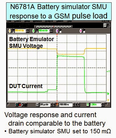
We include programmable resistance in the above mentioned DC power supplies as they are battery simulators.  By being able to program a series output resistance these power supplies are able to better simulate the voltage response of a battery, as shown in Figure 3.


Figure 3: N6781A battery simulator DC source powering a GPRS handset during transmit

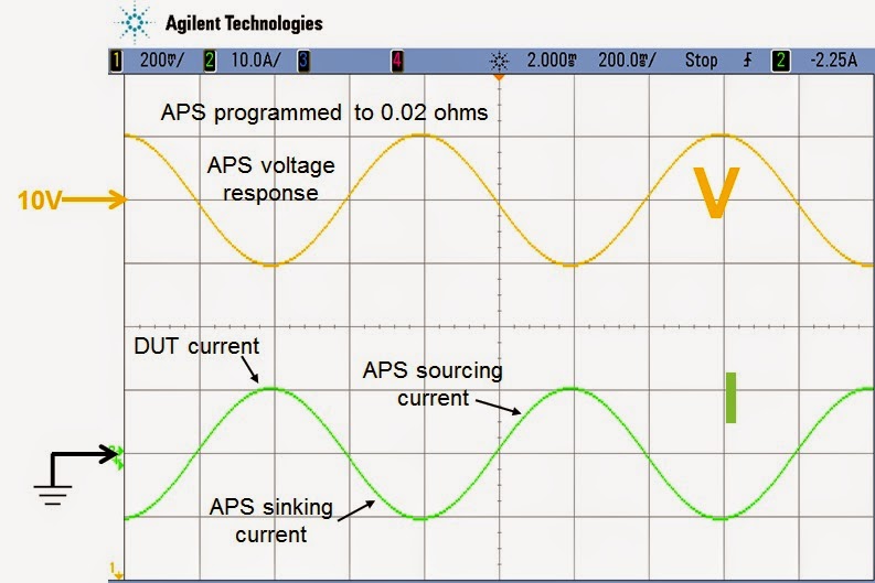
While the 663xxA and N6781A are fairly low power meant to simulate batteries for handheld mobile devices, The N69xxA and N79xxA APS units are 1 and 2 KW power supplies meant to simulate much larger batteries used in things like satellites, robotics, regenerative energy systems, and a number of other higher power devices. Figure 4 shows the voltage response of an N7951A 1 KW APS unit programmed to 20 milliohms output impedance, having a +/- 10 amp peak sine wave load current applied to its output.


Figure 4: N7951A 1 KW APS DC source voltage response to sine wave load

Programmable series output resistance is one more way a specialized DC source helps improve performance and test results, in this case doing a better job simulating the battery that ultimately powers the device under test.

Monday, March 31, 2014

Use the FETCH Command to Minimize Your Measurement Time

Hi everyone,

I am back again with another programming tip for you.  A neat feature on some of our products that many people many not know about is the ability to fetch measurements from a previous acquisition.  Quite a few of our power supplies and loads (the N6700 modules, the N7900 APS power supplies, the 681xB AC Sources, the N3300 loads, and probably some others that I am probably forgetting) have the ability to acquire voltage and current measurements at the same time.  This is done using the FETCH command (in my little example snippets I use the SCPI short form of FETC).  In a previous blog post I used this command to read back an array of current measurements (see Inrush Current Measurements).  In that command, I use a FETCH command to retrieve a triggered measurement.  

There is another, very useful way to use the FETCH commands.  I am not really sure what the best way to phrase it so I am going to take a shot and then illustrate with an example.  When you send a measure command (say for voltage), the measurement system will also acquire the other measurement (in this case current) and you can send a FETCH command to retrieve that acquired data.   Here is a very small example with some comments (all these commands tested on a N7952A Advanced Power System):

Example Snippet 1:
MEAS:VOLT? -> This will start a new acquisition and take the measurements 
<read back the voltage measurement data>
FETC:CURR? -> This will return the current measured during the voltage measurement above
<read back fetched current measurements>

Since we have voltage and current measurements, the instrument can calculate power:
FETC:POW? -> P=V*I
<read back calculated power>

Please note that you can do this with arrays as well. 

How can this save me time in my program you ask?  Well these power supplies all have built in digitizers that you can access with some programming commands.  The default measurement (at 60 Hz line frequency) is 3255 points measured at 5.12 us per point.  That is a total measurement time of  16.67 ms.  You have the ability to change this to fit your needs though.  You can measure up to 512 Kpoints at up to 40,000 s per point.  Every time you send a measure command you need to wait for the measurement to complete.  For instance:

Example Snippet 2:
MEAS:VOLT?
<read back the voltage measurement data> 
MEAS:CURR? 
<read back the current measurement data>

You will need to wait for two acquisition periods because you are initiating two separate measurements.  In the first example snippet, only the MEAS:VOLT? is initiating a measurement, the FETC:CURR is just reading data out of the instrument.    The downside is that the data that you fetch is going to be of the same age as the last measurement you did so if you need something newer, you need to do a new measurement.  Overall though I think that FETCH is a very useful command.  

I hope people find this useful.  Let us know if you have any questions by using the comments.