Showing posts with label voltage level. Show all posts

Friday, November 7, 2014

Providing effective protection of your DUT against over voltage damage during test

The two most common ways DUTs can be electrically damaged during test are from current-related events or voltage-related events that mange to over-stress the DUT. Sometimes the cause can be an issue with the DUT itself. Other times it can be an issue stemming from the test system. The most common voltage-related damage to a DUT is an over voltage event, beyond a maximum level the DUT can safely tolerate. While there are a number of things that can cause this, most invariably it was an issue with the test system power supply, either from inadvertently being set too high or from an internal failure.

To protect against accidental over voltage damage, test system power supplies incorporate an over voltage protect (OVP) system that quickly shuts down the output upon detecting the voltage has gone above a preset threshold value. More details about OVP have been written about here in a previous posting “Overvoltage protection: some background and history”(click here to review).

The critical thing about over voltage damage is, in most all cases, that it is virtually immediate once the voltage threshold where damage to the DUT occurs is exceeded. It is therefore imperative that you optimize the test set up and settings in order to provide effective protection of your DUT against over voltage damage during test. To start with, the OVP trip threshold needs to be set at a reasonable amount below the threshold where DUT damage occurs and at the same time be set to a reasonable amount above the maximum expected DUT operating voltage. This is depicted in Figure 1.


Figure 1: OVP set point

However, to understand what are “reasonable amounts” above the maximum operating voltage and below the DUT damage voltage levels you need to take into account the dynamic response characteristics of the power supply output and OVP system, as depicted in Figure 2.


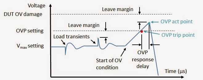
Figure 2: Power supply output and OVP dynamic response characteristics

It is important to have adequate margin above the maximum operating voltage to account for transient voltages due to the DUT drawing current from the power supply and resulting voltage response of the power supply in correcting for this loading, in order to prevent false OVP tripping. It is likewise important to adequate margin below the DUT damage threshold as it takes a small amount of time, in the range of 10’s to 100’s of microseconds, for the OVP system to start shutting down the power supply’s output once the OVP trip point has been crossed. At the same time the power supply typically has a maximum rate the output voltage can slew in. In practice these “reasonable amounts” typically need to be a few tenths to several tenths of a volt as a minimum.

Generally these margins are not difficult to manage, except when the DUT’s operating voltage is very small or the DUT operating current is very large producing a correspondingly large voltage drop in the power supply wiring. This is because the OVP is traditionally sensed on power supply’s output power terminals, so that it provides protection regardless of what the status and condition of the remote voltage sense wiring connection is. To improve on this we also provide OVP sensing on the remote sensing wires as an alternative to, or in addition to, the traditional sensing on the output power terminals. More details about this are described in another posting here “Protect your DUT: Use sense leads for over voltage protection (OVP)”(click here to review).

By following these suggestions you should be able to effectively protect your DUT against over voltage damage during test as well!

Wednesday, December 5, 2012

Power supply current source-to-sink crossover characteristics


A two-quadrant power supply is traditionally one that outputs unipolar voltage but is able to both source as well as sink current. For a positive polarity power source, when sourcing current it is operating in quadrant 1 as a conventional power source. When sinking current it is operating in quadrant 2 as an electronic load. Conversely, a negative polarity two-quadrant  power source operates in quadrants three and four. Further details on power supply operating quadrants are provided in a recent posting here in ‘Watt’s Up?”, What is a bipolar (four-quadrant) power supply? Often a number of questions come up when explaining two-quadrant power supply operation, including:
  • What does it take to get the power supply operating as a voltage source to cross over from sourcing to sinking current?
  • What effect does crossing over from sourcing to sinking current have on the power supply’s output?


For a two-quadrant voltage source to be able to operate in the second quadrant as an electronic load, the device it is normally powering must also be able to source current and power as well as normally draw current and power. Such an arrangement is depicted in Figure 1, where the device is normally a load, represented by a resistance, but also has a charging circuit, represented by a switch and a voltage source with current-limiting series resistance.


Figure 1: Voltage source and example load device arrangement for two-quadrant operation.

There is no particular control on a two-quadrant power supply that one has to change to get it to transition from sourcing current and power to sinking current and power from the device it is normally powering. It is simply when the source voltage is greater than the device’s voltage then the voltage source will be operating in quadrant one sourcing power and when the source voltage is less than the device’s voltage the voltage source will be operating in quadrant two as an electronic load. In figure 1, during charging the load device can source current back out of its input power terminals as long as the charger’s current-limited voltage is greater than the source voltage.

It is assumed that load device’s load and charge currents are lower than the positive and negative current limits of the voltage source so that the voltage source always remains in constant voltage (CV) operation. A step change in current is the most demanding from a transient standpoint, but as the voltage source is always in its constant voltage mode it handle the transition well as its voltage control amplifier is always in control. This is in stark contrast to a mode cross over between voltage and current where different control amplifiers need to exchange control of the power supply’s output. In this later case there can be a large transient while changing modes. See another posting, Why Does My Power Supply Overshoot at Current Limit? Insights on Mode Crossover” for further information on this.  There is a specification given on voltage sources which quantifies the impact one should expect to see from a step change in current going from sourcing current to sinking current, which is its transient voltage response.  A transient voltage response measurement was taken on an N6781A two-quadrant DC source, stepping the load from 0.1 amps to 1.5 amps, roughly 50% of its rated output current.


Figure 2: Agilent N6781A transient voltage response measurement for 0.1A to 1.5A load step

However, the transient voltage response shown in Figure 2 was just for sourcing current. With a well-designed two-quadrant voltage source the transient voltage response should be virtually unchanged for any step change in current load, as long as it falls within the voltage source’s current range.  The transient voltage response for an N6781A was again capture in Figure 3, but now for stepping the load between -0.7A and +0.7A.


Figure 3: Agilent N6781A transient voltage response measurement for -0.7A to +0.7A load step

As can be seen in Figures 2 and 3 the voltage transient response for the N6781A remained unchanged regardless of whether the stepped load current was all positive or swung between positive and negative (sourcing and sinking).

While the transient voltage response addresses the dynamic current loading on the voltage source there is another specification that addresses the static current loading characteristic, which is the DC load regulation or load effect.  This is a very small effect on the order of 0.01% output change for many voltage sources. For example, for the N6781A the load effect in its 6 volt range is 400 microvolts for any load change. In the case of the N6781A being tested here the DC change was the same for both the 0.1 to 1.5 amp step and the -0.7 to +0.7 amp step change.


There are two more scenarios which will cause a two-quadrant power supply transition between current sourcing and sinking.  The first is very similar to above with the two-quadrant power supply operating in constant voltage (CV) mode, but instead of the DUT changing, the power supply changes its voltage level instead.  The final scenario is having the two-quadrant power supply operating in constant current with the DUT being a suitable voltage source that is able to source and sink power as well, like a battery for example. Here the two-quadrant power supply can be programmed to change from a positive current setting to a negative current setting, thus transitioning between sourcing and sinking current again, and its current regulating performance is now a consideration.  Both good topics for future postings!

Wednesday, February 22, 2012

On DC Source Voltage and Current Levels and (Compliance) Limits Part 1: When levels and limits are one and the same

I was having a discussion with a colleague about constant current operation versus constant voltage operation and the distinction between level settings and limit settings the other day. “The level and limit settings are really the same thing!” he claimed. I disagreed. We each then made ensuing arguments in defense of our positions.

He based his argument on the case of a DC power supply that has both constant voltage and constant current operation. I’ll agree that is a reasonable starting point. As a side note there is a general consensus here that if it isn’t a true, well regulated constant voltage or constant current, whether settable or fixed, then it is simply a limit, not a level setting, end of story. He continued “if the load on the power supply is such that it is operating in constant voltage, then the voltage setting is the level setting and the current setting is the limit setting. If the load increases such that the power supply changes over from constant voltage operation into constant current operation then the voltage setting is becomes the limit setting and the current setting becomes the level setting!” (See figure 1.) He certainly has a good point! For your more basic DC power supply that only operates in quadrant 1 capable of sourcing power only, the current and voltage settings usually interchangeably serve as both the level and compliance limit setting, depending on whether the DC power supply is operating in constant voltage or constant current. The level and compliance limit regulating circuits are one and the same. Likewise with the programming, there are only commands to set the voltage and current levels. There are not separate commands for the limits. I might be starting to lose grounds on this discussion!
Figure 1: Unipolar single quadrant DC source operation

However, all is not lost yet. The DC power supply world is often more complicated than just this unipolar single quadrant operation just presented. Watch for my second part on when the levels and limits are not necessarily one and the same.