Wednesday, May 15, 2013

Power Factor and Active Power Factor Correction for Switched-mode Power Supplies


In my previous posting “More on Early Power Supply Preregulator Circuits” SCRs served to provide basically line frequency switched-mode operation for efficient power conversion and regulation in earlier mixed-topology DC power supply designs. Now that high frequency switched-mode power conversion circuits have long been highly refined, are physically much smaller, and are extremely cost effective they have become the game-changer. They can be used as a preregulator for mixed-topology DC power supply designs, as well as the complete DC power supply from the AC input to the regulated DC output, right? Well almost “yes”. They do bring all those of benefits over line frequency operation. As they can span a much wider range of AC input another benefit they bring is to eliminate the need for a complex AC line switch arrangement for the wide range of AC voltages needed.

It was recognized that one downside of high frequency switched-mode conversion is the AC input suffered from rather low power factor (PF). PF is the ratio of the real power to the apparent power. Low PFs cause increased losses in the AC power distribution system. Not only was it low, it was very non-linear, drawing current having high levels of odd harmonics. It turns out the third harmonic in particular can be additive, causing excessive current through the neutral line of AC power distribution systems. The reason for the low and non-linear PF is that the AC input of a high frequency switched-mode conversion circuit is a diode bridge feeding a large, high voltage, bulk storage capacitor, as shown in Figure 1. This non-linear load draws large peaks of current over short portions of the AC line period.


Figure 1: Non-linear AC load input of a high frequency switch-mode power converter circuit

As more and more electronic equipment was making use of switch-mode DC power supplies, minimum PF standards were established for products above a certain power rating, to avoid causing problems with the AC power distribution system. To meet the standards switch-mode DC power supplies above a certain power rating have had to incorporate power factor correction (PFC) into their AC inputs. While a few different approaches can be taken for adding PFC, most switch-mode DC power supplies incorporate a specialized switched-mode boost converter stage for providing active PFC. The active PFC stage is placed between the input rectifier bridge and bulk storage capacitor as depicted in Figure 2. An active PFC stage is designed to draw AC current in phase and in proportion to the AC voltage, typically providing PFs in a range of 0.95 to 0.99, which is comparable to a nearly purely resistive load!


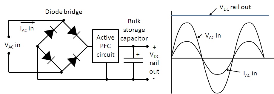
Figure 2: Active PFC circuit in typical switched-mode DC power supply

While adding active PFC to a switch-mode DC power supply increases complexity, cost, and power loss somewhat, the overall combination of benefits of a switch-mode DC power supply with active PFC, either stand-alone or as a preregulator, is hard to beat!

Friday, May 10, 2013

More on Early Power Supply Preregulator Circuits


In my last posting “Ferroresonant Transformers as Preregulators in Early DC Power Supplies “, I introduced the concept of preregulators as a means of improving the efficiency of power supplies.  While a linear regulator provides excellent performance as a power supply, it has to dissipate all the additional power resulting from the voltage drop across it as it takes up the difference between the output voltage setting and the unregulated DC voltage at its input. This voltage difference becomes quite large for high-line AC input voltage levels, as well as low DC output voltage settings when the power supply has an adjustable output. A linear power supply becomes quite inefficient and physically large, having to dissipate a lot of power in comparison to what it provides at its output.  A preregulator helps to mitigate this disadvantage while still retaining the performance advantages of a linear output stage.

The ferroresonant transformer was a clever device and was an effective means of compensating for variance in the AC input voltage, but its output was fixed so it did not do anything for compensating for low DC output voltage settings when the power supply had an adjustable output.  A far more common type of preregulator circuit often used was an SCR preregulator circuit, depicted in Figure 1.


Figure 1: Constant voltage power supply with SCR preregulator

The SCR is a four layer diode structure. Unlike a conventional diode it does not conduct in the forward direction until a signal current is applied to its gate input. It then latches on and remains conducting in its forward direction. It does so until the forward bias voltage is removed or reversed and it resets. In the reverse direction it is the same as a conventional diode.  By replacing two of the conventional diodes in the full wave diode bridge with SCRs as shown in Figure 1, the DC voltage feeding into the linear regulator output stage can now be preregulated.  The preregulator control circuit senses the voltage across the series linear regulator output stage. For each half cycle of the line frequency it adjusts the firing angle of the SCRs in order to adjust the DC voltage at the input of the linear regulator so that the voltage across the linear regulator remains constant, compensating for the load and output voltage level setting accordingly. Figure 2 shows how changing the firing angle of the SCRs changes the output voltage and current delivered by the SCR preregulator circuit.


Figure 2: SCR firing angle control of the preregulator’s output

In all, an SCR preregulated power supply with a linear output stage provided a good balance of efficiency, performance, and cost making its topology well suited for DC power supplies for a variety of lab and industrial applications for the time.  Still, time marches on and high frequency switching-based topologies have come to dominate for the most part, due to a number of advantages they bring. As a matter of fact it is not uncommon today to find a switching power supply serving as a preregulator as well!


Reference: Agilent Technologies DC Power Supply Handbook, application note AN-90B, part number 5952-4020 “Click here to access”

Tuesday, April 30, 2013

How do I measure inrush current with an Agilent DC Power Supply?

Hello everybody! I want to build on my blog post from last month.  This month, we are going to discuss how to measure inrush current using the DC Power Analyzer’s scope function as well as the digitizer feature that is available on some of our system power supplies.

Measuring inrush current is a task that many customers that use DC Power Supplies want to accomplish.  When you are doing this test on the bench, the N6705B DC Power Analyzer (DCPA) is your best bet.  The DCPA has the scope feature which makes this a breeze.  One of the great things about Agilent power supplies is that they can measure current directly, without the need for a current probe. Some of our supplies have very high current measurement accuracy as well so you can get an accurate representation of your current.

In the below screenshot, I just had a capacitor connected to the output of the supply.  I set a voltage arbitrary waveform that went from 0 V to 20 V with the voltage slew set for the maximum.  I set the scope to trigger on the Arb run/stop key so that when I hit the key, both the arbitrary waveform and the scope triggered.  After I acquired the waveform, I used the markers to get the maximum current.  That number is our inrush current.   


As I said earlier, DCPA is geared towards bench use.   The graphical scope makes this task pretty easy.  Many of our system supplies (as well as the DCPA) have a digitizer feature that you can access using the SCPI programming interface.  The digitizer will sample the output using settings that you provide it.  These settings are: the number of points, the time interval between points, and the number of pretrigger points that you acquire.  In the N678xA SMU modules, the time interval is as low as 5.12 us and the number of points is as high as 512kpoints.  Here is a list of commands to set up the digitizer (written for the N67xx supplies) as well as some comments.

Set the digitizer to measure current:
 SENS:FUNC:CURR ON,(@1)

Set the number of pretrigger points, a negative value represents points taken before the trigger:
SENS:SWE:OFFS:POIN -100,(@1)

Set the total number of points to acquire:
SENS:SWE:POIN 5000,(@1)

Set the time interval between points:
SENS:SWE:TINT 0.000020,(@1)

Set the measurement trigger source to bus:
TRIG:ACQ:SOUR BUS,(@1)

 Initiate the measurement trigger system
INIT:ACQ (@1)

Send a trigger:
*TRG

Using this code, once the trigger is sent, the measurement system will acquire 5000 points at a time interval of 20 us while taking 100 pretrigger points. 

After the measurement occurs, you read the current back using:
FETC:ARR:CURR? (@1)

Once you have the array of current measurements, you can do any normal calculation that you can do on any array.  To measure inrush, you want to find the maximum current in the array.  This peak will be your inrush current.  I wrote a program that followed the exact same steps that I used on the scope above (setting up a step that went from 0 to 20 V and synchronizing triggers) and measured a maximum of 1.07748 A.  As you can see, I got a similar result from the two different approaches.

That is all that I have this month.  I hope that it is useful information.  If you have any questions at all please feel free to ask them in our comments.

Friday, April 26, 2013

How to read your DC power supply’s data sheet

When you have to select a programmable DC power supply to power your device under test (DUT), you will have many power supply vendors to choose from. To narrow your selection, you will likely read the data sheets associated with the power supplies you are interested in. While some of the basic information about the power supplies presented on the data sheets will be similar, you will also find different specification descriptions from different power supply vendors. To ensure you are considering the right specs, it is best to start with a good understanding of your DUT’s power requirements. Start with your DUT’s required maximum input voltage, current, and power. Think about whether or not you need to supply dynamic input voltages to your DUT and about how accurate the DUT input voltage needs to be.  Then consider what power-related measurements you will need to make.


Once you know your DUT’s power requirements, you can begin to peruse the specs in various power supply data sheets to find one that meets your needs. Most likely, you will be considering specs such as:
  • DC output ratings
    • These show the maximum voltage, current, and power available from the power supply. Make sure your DC input requirements are within these values. 
  • Output noise
    • This specification describes the deviations in the DC output voltage, typically expressed as peak-to-peak volts and rms volts. If your DUT is sensitive to noise, be sure to choose a low noise power supply.
  • Load regulation (also called load effect)
    • This spec shows how much the steady-state output voltage can change when the load current changes. If you want the input voltage to your DUT to vary very little when your DUT current changes, choose a power supply with low load regulation.
  • Load transient recovery time
    • This is the time for the output voltage to recover to within a settling band around the steady-state value when the load current changes. If your DUT is sensitive to large short-term input voltage changes, choose a power supply with a short load transient recovery time.
  • Line regulation (also called line effect, source regulation, or source effect)
    • This spec shows how much the steady-state output voltage can change when the power supply’s AC input line voltage changes. If you want the input voltage to your DUT to vary very little when your AC line voltage changes, choose a power supply with low line regulation.
  • Programming accuracy
    • This spec shows how much the steady-state output voltage can vary from its programmed (set) value. If you want the input voltage to your DUT to be very precisely controlled, choose a power supply with a low programming accuracy. (Most “programming accuracy” specs are really describing the maximum possible “programming error”, so you want this number to be low.)
  • Measurement accuracy
    • This spec shows how much the steady-state measurements (voltage or current) can vary from the actual output value. If you are counting on measuring your DUT’s input voltage or current with high accuracy, choose a power supply with low measurement accuracy. (Most “measurement accuracy” specs are really describing the maximum possible “measurement error”, so you want this number to be low.)
One of my colleagues, Kevin Cavell, wrote an article entitled “How to Read Your DC Power Supply’s Data Sheet” that appeared in the March, 2013 issue of Design World addressing in more detail many of these considerations. Here is a link to the on-line version:
http://www.designworld-digital.com/designworld/201303#pg71

The same article can be accessed here:
http://www.powersupplytips.com/how-to-read-your-dc-power-supplys-data-sheet

Finally, here is a link to Kevin’s application note – the article was based on this app note:
http://cp.literature.agilent.com/litweb/pdf/5991-2293EN.pdf

Kevin’s app note uses examples from the data sheets for a Sorenson power supply and an Agilent power supply. You will notice that the magazine articles refer to these as Power Supply A and Power Supply B.


Tuesday, April 23, 2013

Ferroresonant Transformers as Pre-regulators in DC Power Supplies


One significant drawback of a linear DC power supply is its efficiency for most applications. You can generally design a linear DC power supply with reasonable efficiency when both the output and input voltage values are fixed. However, when either or both of these vary over a wide range, after assuring the DC power supply will properly regulate at low input voltage and/or high output voltage, it then has to dissipate considerable power the other extremes.

For DC power supplies running off an AC line, having to accommodate a fairly wide range of AC input voltage is a given. A 35% increase in line voltage from the minimum to the maximum value is not uncommon. Today’s high frequency switching based power supplies have resolved the issue of efficiency as a function of input line voltage variance. However, prior to widespread adaptation of high frequency switching DC power supplies, variety of different types of low-frequency pre-regulators were developed for linear DC power supplies

What is a pre-regulator? A pre-regulator is a circuit that provides a regulated voltage to the linear output stage from an unregulated voltage derived from the AC line voltage, with little loss of power. Although not nearly as commonly used as other pre-regulator schemes, on rare occasion ferroresonant transformers were used as an effective and efficient pre-regulator in DC power supplies.

What is a ferroresonant transformer? It is similar to a regular transformer in that it transforms AC voltage through primary and secondary windings. Unlike a regular transformer however, once it reaches a certain AC input voltage level it starts regulating its AC output voltage at a fixed level even as the AC input voltage continues to rise, as depicted in Figure 1. Ferroresonant transformers are also commonly called constant voltage transformers, or CVTs.


Figure 1: Ferroresonant transformer input-output transfer characteristic

The ferroresonant transformer employs a rather unique magnetic structure that places a magnetic shunt leakage path between the primary and secondary windings. This structure is illustrated in Figure 2. This way only part of the transformer structure saturates at a higher fixed peak voltage level during each AC half cycle. When part of the core magnetically saturates, the primary and secondary windings are effectively decoupled. The AC capacitor on the secondary side resonates with existing inductance. This provides the carry-over energy to the load during this magnetically saturated phase, holding up the voltage level. The resulting waveform is a clipped sine wave with a fairly high level of harmonic distortion as a result. Some more modern designs include additional filtering that can bring the harmonic distortion down to just a few percent however.


Figure 2: Ferroresonant transformer structure

A ferroresonant transformer has some very appealing characteristics in addition to output voltage regulation:
  • Provides isolation from line spikes and noise that is normally coupled through on conventional transformers
  • Provides protection from AC line voltage surges
  • Provides carry over during momentary AC line drop outs that are of a fraction of a line cycle
  • Limits its output current if short-circuited
  • Extremely robust and reliable


Because of a number of other tradeoffs it is unlikely that you will find them in a DC power supply today. High frequency switching designs pretty much totally dominate in performance and cost. Ferroresonant transformer design tradeoffs include:
  • Large physical size
  • Relatively expensive and specialized
  • Limited to a specific line frequency as it resonates at that frequency


So, even though you are very unlikely to encounter a ferroresonant transformer in a DC power supply today, it’s interesting to see there still appears to be a healthy demand for ferroresonant transformers as AC line conditioners in a wide range of sizes, up to AC line power utility sizes.  Their inherent simplicity and robustness is hard to beat when long term, maintenance-free, reliable service is paramount, and AC line regulation in many regions around the world cannot be counted on to be well controlled.

Monday, April 8, 2013

Why would a DC power supply have RMS current readback?


During a conversation with a colleague at work one day the topic of having RMS current readback on DC power supplies came up. It is a measurement capability we have on a number of our system DC power supplies. He posed the question: Why the reason for having such a capability? I actually had not been involved with the original investigations identifying what reasons this was added so I instead had to rely on my intuition. That’s not always a good thing but it did help me out this time at least!

He had argued that since you are feeding a fixed DC voltage into the device you are powering, the power consumption is going to be a product of the DC (average) voltage and DC (average) current, regardless of whether the current is purely DC, or if it is dynamic, having a substantial amount of AC content. This is true, as I have illustrated in figure 1, comparing purely DC and pulsed currents being drawn by a load. For purely DC current the DC and RMS values are the same. In comparison, for a pulsed current the RMS value is greater the DC value. Regardless, the RMS current value does not factor into the overall power consumption of the DUT here. The power consumption is still the product of the DC voltage and current.


Figure 1: Comparing power consumption of a DC powered DUT drawing constant and pulsed currents

So why provide an RMS current measurement? Well there can be times when this can prove useful, even when the DUT is powered by a fixed DC voltage. Consider the scenario depicted in Figure 2.


Figure 2: Properly sizing a protection fuse on a DC powered device

Many products incorporate fuses to protect from over-current and subsequent damage, usually brought on due to misuse or component failure. Fuses are rated by their RMS current handling, not the DC current. In the case of the pulsed loading the RMS current is twice the DC current and the resulting power in the fuse is four times that for a constant current.  If the fuse was selected based on the DC current value it would most certainly fail well below the required operating level!

My colleague conceded that this fuse example was a legitimate case where RMS current measurement would indeed be useful. Maybe it was not a frivolous capability after all. No doubt sizing fuses is just one of many reasons why RMS measurement on DC products can be useful!

Sunday, March 31, 2013

Remote sensing can affect load regulation performance


Back in September of 2011, I posted about what load effect was (also known as load regulation) and how it affected testing (see http://powersupplyblog.tm.agilent.com/2011/09/what-is-load-effect-and-how-does-it.html). The voltage load effect specification tells you the maximum amount you can expect the output voltage to change when you change the load current. In addition to the voltage load effect specification, some power supplies have an additional statement in the remote sensing capabilities section about changes to the voltage load effect spec when using remote sensing. These changes are sometimes referred to as load regulation degradation.

For example, the Agilent 6642A power supply (20 V, 10 A, 200 W) has a voltage load regulation specification of 2 mV. This means that for any load current change between 0 A and 10 A, the output voltage will change by no more than 2 mV. The 6642A also has a remote sensing capability spec (really, a “supplemental characteristic”). It says that each load lead is allowed to drop up to half the rated output voltage. The rated output voltage for the 6642A is 20 V, so half is 10 V meaning when remote sensing, you can drop up to 10 V on each load lead. Also included in the 6642A remote sensing capability spec is a statement about load regulation. It says that for each 1 volt change in the + output lead, you must add 3 mV to the load regulation spec. For example, if you were remote sensing and you had 0.1 ohms of resistance in your + output load lead (this could be due to the total resistance of the wire, connectors, and any relays you may have in series with the + output terminal) and you were running 10 A through the 0.1 ohms, you would have a voltage drop of 10 A x 0.1 ohms = 1 V on the + output lead. This would add 3 mV to the load regulation spec of 2 mV for a total of 5 mV.

There are other ways in which this effect can be shown in specifications. For example, when remote sensing, the Agilent 667xA Series of power supplies expresses the load regulation degradation as a formula that includes the voltage drop in the load leads, the resistance in the sense leads, and the voltage rating of the power supply. Output voltage regulation is affected by these parameters because the sense leads are part of the power supply’s feedback circuit, and these formulas describe that effect:


One more example of a way in which this effect can be shown in specifications is illustrated by the Agilent N6752A. Its load effect specification is 2 mV and goes on to say “Applies for any output load change, with a maximum load-lead drop of 1 V/lead”. So the effect of load-lead drop is already included in the load effect spec. Then, the remote sense capability section simply says that the outputs can maintain specifications with up to a 1 V drop per load lead.

When you are choosing a power supply, if you want the output voltage to be very well regulated at your load, be sure to consider all of the specifications that will affect the voltage. Be aware that as your load current  changes, the voltage can change as described by the load effect spec. Additionally, if you use remote sensing, the load effect could be more pronounced as described in the remote sensing capability section (or elsewhere). Be sure to choose a power supply that is fully specified so you are not surprised by these effects when they occur.