Showing posts with label output impedance. Show all posts

Thursday, June 20, 2013

How can I measure output impedance of a DC power supply?

In my last posting “DC power supply output impedance characteristics”, I explained what the output impedance characteristics of a DC power supply were like for both its constant voltage (CV) and constant current (CC) modes of operation. I also shared an example of what power supply output impedance is useful for. But how does one go about measuring the output impedance of a DC power supply over frequency, if and when needed?

There are a number of different approaches that can be taken, but these days perhaps the most practical is to use a good network analyzer that will operate at low frequencies, ranging from 10 Hz up to 1 MHz, or greater, depending on your needs. Even when using a network analyzer as your starting point there are still quite a few different variations that can be taken.

Measuring the output impedance requires injecting a disturbance at the particular frequency the network analyzer is measuring at. This signal is furnished by the network analyzer but virtually always needs some amount of transformation to be useful. Measuring the output impedance of a voltage source favors driving a current signal disturbance into the output. Conversely, measuring the output impedance of a current source favors driving a voltage signal disturbance into the output. The two set up examples later on here use two different methods for injecting the disturbance.

The reference input “R” of the network analyzer is then used to measure the current while the second input “A” or “T” is used to measure the voltage on the output of the power supply being characterized. Thus the relative gain being measured by the network analyzer is the impedance, based on:
zout = vout/iout = (A or T)/R
The output voltage and current signals need to be compatible with the measurement inputs on the network analyzer. This means a voltage divider probe may be needed for the voltage measurement, depending on the voltage level, and a resistor or current probe will be needed to convert the current into an appropriate voltage signal. A key consideration here is appropriate scaling constants need to be factored in, based on the gain or attenuation of the voltage and current probes being used, so that the impedance reading is correct.


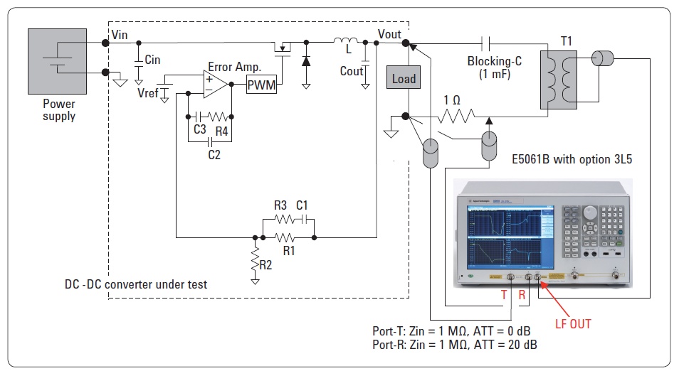
Figure 1: DC power supply output impedance measurement with the Agilent E5061B

One example set up using the Agilent E5061B network analyzer is shown in Figure 1, taken from page 15 of an Agilent E5061B application note on testing DC-DC converters, referenced below. Here the disturbance is injected in through an isolation transformer coupled across the power supply output through a DC blocking capacitor and a 1 ohm resistor. The 1 ohm resistor is doing double duty in that it is changing the voltage disturbance into a current disturbance and it is also providing a means for the “R” input to measure the current. The “T” input then directly measures the DC/DC converter’s (or power supply’s) output voltage.

A second, somewhat more elaborate, variation of this arrangement, based on using a 4395A network analyzer (now discontinued) has been posted by a colleague here on our Agilent Power Supply forum: “Output Impedance Measurement on Agilent Power Supplies”. In this set up the disturbance signal from the network analyzer is instead fed into the analog input of an Agilent N3306A electronic load. The N3306A in turn creates the current disturbance on the output of the DC power supply under test as well as provide any desired DC loading on the power supply’s output. The N3306A can be used to further boost the level of disturbance if needed. Finally, an N278xB active current probe and matching N2779A probe amplifier are used to easily measure the current signal.

Hopefully this will get you on your way if the need for making power supply output impedance ever arises!


Reference: “Evaluating DC-DC Converters and PDN with the E5061B LF-RF Network Analyzer” Application Note, publication number 5990-5902EN (click here to access)

Monday, June 10, 2013

DC power supply output impedance characteristics

In a previous posting; “How Does a Power Supply regulate It’s Output Voltage and Current?” I showed how feedback loops are used to control a DC power supply’s output voltage and current.  Feedback is phenomenally helpful in providing a DC power supply with near-ideal performance. It is the reason why load regulation is measured in 100ths of a percent. A major reason for this is it bestows the power supply, if a voltage source, with near zero impedance, or as a current source, with high output impedance. How does it do this?

The impedance of a typical DC power supply’s output stage (like the conceptual one illustrated in the above referenced posting) is usually on the order of an ohm to a couple of ohms. This is the open-loop output impedance; i.e. the output impedance before any feedback is applied around the output.   If no feedback were applied we would not have anywhere near the load regulation we actually get. However, when the control amplifier provides negative feedback to correct for changes in output when a load is applied, the performance is transformed by the ratio of 1 + T, where T is loop gain of the feedback system. As an example, the output impedance of the DC power supply operating in constant voltage becomes:

Zout (closed loop) = Zout (open loop) / (1+T)

The loop gain T is approximately the gain of the operational amplifier times the attenuation of the voltage divider network. In practical feedback control systems the gain of the amplifier is quite large at and near DC, possibly as high as 90 dB of gain. This reduces the power supply’s DC and low frequency output to just milliohms or less, providing near ideal load regulation performance. Another factor in practical feedback control systems is the loop gain is rolled off in a controlled manner with increasing frequency in order to maintain stability. Thus at higher frequency the output impedance of a DC power supply operating as a voltage source increases towards its open loop impedance value as the loop gain decreases. This is illustrated in the output impedance plots in Figure 1, for the Agilent 6643A DC power supply.


Figure 1: Agilent 6643A 35V, 6A system DC power supply output impedance

As can be seen in Figure 1, for constant voltage operation, the 6643A DC power supply is just about 1 milliohm at 100 Hz, and exhibits an inductive output characteristic with increasing frequency as the loop gain decreases.

As also can be seen in Figure 1, feedback control works in a similar fashion for constant current operation. While a voltage source ideally has zero output impedance, a current source ideally has infinite impedance.  For constant current operation the 6643A DC power supply exhibits 10 ohms impedance at 100 Hz and rolls off in a capacitive fashion as frequency increases. However, for the 6643A, it is not so much the constant current control loop gain dropping off with frequency but the output filter capacitance dominating the output impedance. While the 6643A can be used as an excellent, well-regulated current source (see posting: “Can a standard DC power supply be used as current source?”) it is first and foremost optimized for being a voltage source. Some output capacitance serves towards that end.


An example of one use for the output impedance plots of a DC power supply is to estimate what the amount of load-induced AC ripple might be, based on the frequency and amplitude of the current being drawn by the load, when powered by power supply operating in constant voltage.

Tuesday, January 8, 2013

The difference between constant current and current limit in DC power supplies


Constant Voltage/Constant Current (CC/CV) Power Supplies
In most of our discussions in “Watt’s Up?” on current limiting we have primarily talked about power supplies as having a constant current (CC) output characteristic. This is what is found in many lab and industrial system power supplies, including most of the power supplies provided by us. Even though the terms often get used interchangeably, there is actually a distinction between constant current and current limit. To help explain this distinction, Figure 1 illustrates the output characteristics of a constant voltage/constant current (CV/CC) power supply.


Figure 1: Operating locus of a CC/CV power supply

Five operating points are depicted in Figure 1:
  1. With no load (i.e. infinite load resistance): Iout = 0 and Vout = Vset
  2. With a load resistance of RL > Vset/Iset: Iout = Vset/RL and Vout = Vset
  3. With a load resistance of RL = Vset/Iset: Iout = Iset and Vout = Vset
  4. With a load resistance of RL < Vset/Iset: Iout = Iset and Vout = Iset*RL
  5. With a short circuit (i.e. zero load resistance): Iout = Iset and Vout = 0


The advantage of a CV/CC power supply is it can be used as either a voltage source or a current source, providing reasonable performance in either mode. The point at which RL = Vset/Iset is the mode crossover point where the power supply transitions between CV and CC operation. For a CV/CC power supply there is a sharp transition between CV and CC operation. Note that for an ideal CV/CC power supply the CV slope is zero (horizontal), indicating zero output resistance for CV operation while the CC slope is infinite (vertical), indicating infinite output resistance for CC operation. Note that this is at DC. How close the slope of each mode is to ideal is what determines quality of load regulation for each.  To achieve good performance for both CV and CC modes requires carefully designed and more complex control loops for each mode. More details about using a power supply as a current source is provided in an earlier posting here, entitled: “Can a standard DC power supply be used as a current source?”

Constant Voltage/Current Limiting Power Supplies
In comparison a constant voltage/current limiting (CV/CL) power supplies are intended to be used only as a voltage source while providing over-current protection for the DUT, as well as protection for the power supply itself. Figure 2 depicts typical output characteristics of a CV/CL power supply.


Figure 2: Operating locus of a CV/CL power supply

In CV/CL power supplies the current limit may be a fixed maximum value or it may be settable. In comparison to Figure 1 CV operation is still the same. However, what is found at the current limit cross-over point there is loss of voltage regulation where the voltage starts falling off. Unlike true CC operation in a CV/CC power supply, CL operation does not typically have as sharply a defined cross-over point and once in CL it may not be tightly regulated between the cross-over and short circuit points. The reason for this is CL control circuits are usually more basic in nature in comparison to a true CC control loop. CL is meant for over-current protection only, not CC operation.  For this reason the correct use of CL is to set its value a bit higher than the maximum current required by the DUT. This assures good voltage regulation for the full range of normal loading. You may find many of the more basic bench power supplies have CV/CL operation and may not be useful as current sources as a result.

Reference: Agilent Technologies DC Power Supply Handbook, application note AN-90B, part number 5952-4020

Friday, April 27, 2012

Can a standard DC power supply be used as a current source?

The quick answer to this question is, yes, most standard DC power supplies can be used as current sources. However, this question deserves more attention, so what follows is the longer answer.

Most DC power supplies can operate in constant voltage (CV) or constant current (CC) mode. CV mode means the power supply is regulating the output voltage and the output current is determined by the load connected across the output terminals. CC mode means the power supply is regulating the output current and the output voltage is determined by the load connected across the output terminals. When operating in CC mode, the power supply is acting like a current source. So any power supply that can operate in CC mode can be used as a current source (click here for more info about CV/CC operation).

Is a standard power supply a good current source?
An ideal current source would have infinite output impedance (an ideal voltage source would have zero output impedance). No power supply has infinite output impedance (or zero output impedance) regardless of the mode in which it is operating. In fact, most power supply designs are optimized for CV mode since most power supply applications require a constant voltage. The optimization includes putting an output capacitor across the output terminals of the power supply to help lower output voltage noise and also to lower the output impedance with frequency. So the effectiveness of a standard power supply as a current source will depend on your needs with frequency.

At DC, a power supply in CC mode does make a good current source. Typical CC load regulation specifications support this notion (click here for more info about load regulation). For example, an Agilent N6752A power supply (maximum ratings of 50 V, 10 A, 100 W) has a CC load regulation specification of 2 mA. This means that the output current will change by less than 2 mA for any load voltage change. So when operating in CC mode, a 50 V output load change will produce a current change of less than 2 mA. If we take the delta V over worst case delta I, we have 50 V / 2 mA = 25 kΩ. This means that the DC output impedance will always be 25 kΩ or more for this power supply. In fact, the current will likely change much less than 2 mA with a 50 V load change making the DC output impedance in CC mode much greater than 25 kΩ.

Of course, a power supply’s effectiveness as a current source should be judged by the output impedance beyond the DC impedance. See the figure below for a graph of the N6752A CC output impedance with frequency:
If the graph continued in the low frequency direction, the output impedance would continue to rise as a “good” current source should. At higher frequencies, the CC loop gain inside the product begins to fall. As the loop gain moves through unity and beyond, the output capacitor in the supply dominates the behavior of the output impedance, so at high frequencies, the output impedance is lower. So how good the power supply is as a current source depends on your needs with frequency. The higher the output impedance, the better the current source. The output impedance also correlates to the CC transient response (and to a much lesser extent, the output programming response time).

The bottom line here is that in most applications, a standard DC power supply can be used in CC mode as a current source.